1643914-1 Tyco Electronics, 1643914-1 Datasheet
1643914-1
Specifications of 1643914-1


1643914-1 Summary of contents
Page 1
... The contacts are available in loose piece only. Only crimp type and threaded contacts are removable. When corresponding with Tyco Electronics Personnel, use the terminology provided in this specification to facilitate your inquiries for information. Basic terms and features of these connectors are provided in Figure 1. ...
Page 2
... Contact Cavities Pin Protector Socket Side Mounting Flange Contact Cavities Pin Protector Crimp Type Figure 1 (end) Tyco Electronics Corporation Mini Drawer Socket Side Pin Side Chamfered Edge Quad Power Socket Side Pin Side 125 Amp Middle Drawer Socket Side Pin Side ...
Page 3
... Customer Drawings for product part numbers are available from the service network. If there is a conflict between the information contained in the Customer Drawings and this specification or with any other technical documentation supplied by Tyco Electronics, call Product Information at the number at the bottom of page 1. 2.4. Specifications Product Specification 108--2285 provides product performance and test information ...
Page 4
... Probe Proof ------ Figure 2 Typical Probe- - Proof Socket Contact Size 0 Protective Cap Figure 3 Tyco Electronics Corporation “A” Connector SOLDER TYPE SOLDER TYPE CONTACT CONTACT POST- - MATE 6.85 [.270] 4.06 [.160] 7.36 [.290] 4.06 [.160] 9 ...
Page 5
... Figure 4 Wire TOOL SELECTOR 89 [20] 4 222 [50] 6 489 [110] 8 979 [220] 1779 [400] ------ 3114 [700] Figure 5 Tyco Electronics Corporation WIRE STRIP WIRE SIZE WIRE SIZE LENGTH 2 RANGE (mm ) +0.51 [+.020] 24--20 0.241--0.616 5.33 [.210] 18--16 0.963--1.23 6.86 [.270] 14--12 1.94--2.98 6 ...
Page 6
... The pc board material shall be glass epoxy (FR--4 or G--10). The pc board thickness range shall be 1.38 through 5.08 mm [.054 through .200 in.]. Dial Indicator Probe Placed Here for Measurement of TIR TIR Wire Wire Figure 6 D Tyco Electronics Corporation WIRE SIZE RANGE TIR MEASUREMENT (AWG) (Max) 20 0.279 [.011] 18--12 0.305 [.012] 10--4 0.762 [.030] 0 762 [ 030] 1/0 m [15 in ...
Page 7
... Figure 7 Tyco Electronics Corporation 6.35 mm [.250 in.] Mounting Hole Dia (4 Places 50.80 [2.000] 24.89 [.980] 33.02 [1.300] 24.89 [.980] 95.25 [3.750] 24 ...
Page 8
... Design the pc board using the dimensions provided in Figure 2.65+0.08 [.104+.003] 6 Plc B = 1.78+0.08 [.070+.003] 12 Plc C = 1.19+0.08 [.047+.003] 32 Plc Recommended PC Board Layout Top Drawer Pin Side B C Top Drawer Socket Side B C Figure 8 (cont’d) Tyco Electronics Corporation Rev D ...
Page 9
... Middle Drawer Socket Side Rev D Figure 8 (cont’d) Tyco Electronics Corporation 75A Middle Drawer Pin Side ...
Page 10
... Mini Drawer Pin Side Lower Drawer Pin Side Lower Drawer Socket Side Figure 8 (cont’d) Tyco Electronics Corporation Mini Drawer Socket Side Rev D ...
Page 11
... CONTACTS 3.81 [0.150] TYP 4X 6.35 [0.25] 33.02 [1.30] 1.91 [0.075] TYP 35.56 8.89 [1.40] [0.390] 9.91 Figure 8 (end) Tyco Electronics Corporation Double Drawer 18.42 [0.725] PC BOARD CUT--OUT 36.32 [1.43] 59.44 [2.34] 85.60 [3.37] 98.29 [3.870] 7X 3.8 [0.150] = 26.67 2X 12.32 [0.485 ...
Page 12
... Over Copper 0.025 mm [.0010 in.] Thick Copper Plating (Ref) (Max Hardness 150 Knoop) Tin- - Lead Plating (Ref) FINISHED HOLE DIAMETER (+0.08 [+.003]) Figure 9 0.51 0.51 [.020] [.020] Standoffs Figure 10 Tyco Electronics Corporation 1.20 [.047] 1.80 [.070] 2.65 [.104] 3.82 [.152] Wire Rev D ...
Page 13
... Figure 12 Tyco Electronics Corporation TEMPERATURE (Maximum) CELSIUS FAHRENHEIT 132 270 100 212 Ambient Room 100 212 100 212 100 212 100 212 100 212 100 212 CONNECTOR RATING CONNECTOR RATING 150A/200A 150A/200A{ 32 125A 24 75A 35A ...
Page 14
... Float Mount Shoulder Screw 10 32 Optional Fixed Mounting for High Power Connectors Only Commercially Available Screw and WasherG Figure 13 Tyco Electronics Corporation Top Drawer and Double Drawer Mini Drawer, Lower Drawer, and 75A/125A Middle Drawer Internally Threaded (6- - 32) Guide Pin Rev D ...
Page 15
... Largest Cable Rev D CONNECTOR Notch in Double Drawer, Top Drawer Guide Post 75A and 125A Middle Drawer, Mini Drawer Figure 14 152.4 [6.0] (Min) Cable Tie Figure 15 Tyco Electronics Corporation “A” MATING DIMENSION “A” (MAX) 12.70 mm [.500 in.] Lower Drawer 10.16 mm [.400 in.] Connector ...
Page 16
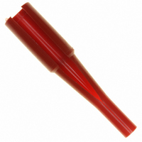
... It is designed for production requirements. Refer to Figure 16. Insertion/Extraction Tool (Typ) (408- - 10159) TOOL INSERTION EXTRACTION PN TIP COLOR TIP COLOR 1643914--1 ------ Red 1643915--1 Yellow White 1643916--1 Blue White 1643917--1 Red ...
Page 17
... MUST NOT ENTER CONTACT WIRE BARREL WIRE INSULATION AND CONDUCTORS MUST BE UNDAMAGED CONNECTOR MUST BE SEATED ON PANEL FIGURE 17. VISUAL AID Tyco Electronics Corporation WIRE CONDUCTOR ENDS MUST BE VISIBLE IN CONTACT SIGHT HOLE FLOAT MOUNTING SCREWS MUST ALLOW MOVEMENT OF CONNECTOR CONTACTS MUST BE LOCKED IN PLACE ...