1. INTRODUCTION
This instruction sheet covers the use of Extraction
Tool 843473–1 which is recommended for removing
crimp, snap–in contacts from AMPMODU MOD I and
MOD IV Receptacle Connectors listed in Catalog
1307819. Read these instructions before attempting
to extract the contacts.
Reasons for reissue are given in SECTION 5,
REVISION SUMMARY.
2. DESCRIPTION
The extraction tip is designed to enter the lance
recess in the front of the housing and depress the
locking lance of the contact.
E
All International Rights Reserved
AMP and Tyco are trademarks. *Trademark
Other products, logos, and company names used are the property of their respective owners.
2003 Tyco Electronics Corporation, Harrisburg, PA
NOTE
NOTE
AMPMODU*
MOD IV
Receptacle
Connector
AMPMODU
MOD I
Receptacle
Connector
All dimensions are in millimeters [with inches in
brackets]. Figures are for reference only and are
not drawn to scale.
The connector includes both the housing and the
contacts while the housing is the material which
forms the encapsulation for the contacts.
Lug
Wire
This controlled document is subject to change.
For latest revision, call the FAX/PRODUCT INFO number.
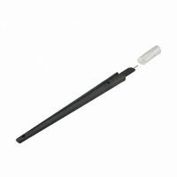
Extraction Tool 843473–1
Figure 1
The lance recess is the cavity located between the
contact and the connector housing. A solid rib
(locking ledge) at the rear of the lance recess cavity
provides a stop for the extraction tool. The housings
are designed to prevent improper insertion of the
contacts which are inserted into the rear of the
housing.
A lug is located on the side of the MOD I housing
which contains the contact locking ledge.
3. EXTRACTION PROCEDURE
Determine which connector contains the contact to be
removed and proceed as follows:
Contact
1. Insert the tool straight into the lance recess until
it bottoms on the locking ledge.
2. Holding the tool and connector in one hand, grip
the wire of the contact with the other hand and pull
the contact out of the back of the connector.
Front of
Connector
Locking Lance
TOOLING ASSISTANCE CENTER 1–800–722–1111
FAX/PRODUCT INFO 1–800–522–6752
For Regional Customer Service, visit our website at
www.tycoelectronics.com
Lance Recess
Locking
Ledge
(Figure 1)
Tip
Instruction Sheet
408–9451
09 SEP 03 Rev B
1 of 2
LOC B