58336-1 Tyco Electronics, 58336-1 Datasheet - Page 4
58336-1
Manufacturer Part Number
58336-1
Description
HEAD (IDC) MODU MTE W/O TL
Manufacturer
Tyco Electronics
Series
AMPMODU® MTEr
Type
Amp Tool Kitr
Specifications of 58336-1
Connector Type
Rectangular
Crimp Handle
A2031-ND, 58075-1-ND, 58338-1-ND, 931800-1-ND
Crimp Or Cable Size
22-30 AWG
Product
Tool Component
For Use With
58075-1 - TOOL HANDLE PNEUMATIC W/O HEAD931800-1 - ELEC PWR UNIT W/O F/TRK OR HD58338-1 - PWR BENCH ASSEMBLY W/O HEADS
Lead Free Status / RoHS Status
Not applicable / Not applicable
Lead Free Status / RoHS Status
na, Not applicable / Not applicable
Other names
58336-1
A28718
A28718


4
2. Prepare the wire, if required, as shown in
Figure 5.
3. Squeeze and hold the trigger (pneumatic
handle) or cam handle (manual handle). Align the
tabs on the carrier strip with the slots in the strip
guide in the terminating head, and push the carrier
strip against the wire inserter.
4. Release the trigger; the product will be indexed
to the first position.
5. Insert an unstripped wire into the wire slot until it
bottoms on the tool base.
6. Center the wire in the wire slot. Squeeze the
trigger or cam handle until the ratchet releases.
7. Release the trigger or cam handle. The wire
inserter will retract and the housing assembly will
advance to the next position.
8. Repeat Steps 5, 6, and 7 until all contacts have
been terminated.
9. Remove the housing assembly from the right
side of the head by grasping the wires as close to
the head as possible.
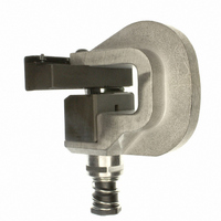
Figure 4
Terminating Head 58336-1
G
CAUTION
CAUTION
WIRE
SIZE,
AWG
NOTE
10. Grasp the carrier strip which connects the
terminated contacts and bend it downward to a 90
angle, and then upward until it snaps off. See
Figure 6.
DISCRETE
Ribbon Cable
WIRE
CABLE PREPARATION LENGTHS
The terminated housing assembly must be
removed from the terminating head before the
next housing assembly to be terminated is
inserted into the head.
The connector may be fed manually through the
terminating head without squeezing the trigger or
cam handle of the handle assembly.
Be careful not to bend contacts during carrier
strip removal. Contacts may be mass-inserted
(with 8-position and smaller housings) before the
carrier strip is removed. The carrier strip may be
removed as described in Step 10. Do not exceed
the 90
contact insertion method, it is very important to
make sure that each contact is locked into
position as described in Step 12.
maximum bend dimension. With either
Figure 5
(Cable Jacket)
JACKETED
CABLE
G
Jacketed Cable
(Slit Length)
RIBBON
CABLE
408-9359
G
B