58336-1 Tyco Electronics, 58336-1 Datasheet - Page 3
58336-1
Manufacturer Part Number
58336-1
Description
HEAD (IDC) MODU MTE W/O TL
Manufacturer
Tyco Electronics
Series
AMPMODU® MTEr
Type
Amp Tool Kitr
Specifications of 58336-1
Connector Type
Rectangular
Crimp Handle
A2031-ND, 58075-1-ND, 58338-1-ND, 931800-1-ND
Crimp Or Cable Size
22-30 AWG
Product
Tool Component
For Use With
58075-1 - TOOL HANDLE PNEUMATIC W/O HEAD931800-1 - ELEC PWR UNIT W/O F/TRK OR HD58338-1 - PWR BENCH ASSEMBLY W/O HEADS
Lead Free Status / RoHS Status
Not applicable / Not applicable
Lead Free Status / RoHS Status
na, Not applicable / Not applicable
Other names
58336-1
A28718
A28718


3.2. Wire Insertion Depth
A. Wire Too Deep in Contact Slot
B. Wire Not Deep Enough in Contact Slot
Rev C
NOTE: 1/6 Turn
Equals 0.20 mm
[.008 in.] Adjustment
1. Remove the head and turn the adjuster 1/6--turn
CLOCKWISE (See Figure 3). This will reduce the
wire insertion depth by approximately 0.20 mm
[.008 in.].
2. Make a test termination according to the
procedure given in Section 4, TERMINATION
PROCEDURE, and inspect the termination in
accordance with Section 5, INSPECTION.
Readjust if required.
Manual Handle Assembly
1. Remove the head and turn the adjuster 1/6--turn
COUNTERCLOCKWISE (See Figure 3). This will
increase wire insertion depth by approximately
0.20 mm [.008 in.].
2. Make a test termination according to the
procedure given in Section 4, TERMINATION
PROCEDURE, and inspect the termination in
accordance with Section 5, INSPECTION.
Readjust if required.
Pneumatic Handle Assembly
1. Increase the air pressure by 69 kPa [10 psi],
and make a test termination according to the
procedure given in Section 4, TERMINATION
PROCEDURE.
2. Check the termination in accordance with
Section 5, INSPECTION.
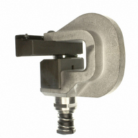
Figure 3
Turn
COUNTERCLOCKWISE for
Deeper Wire Insertion
Turn CLOCKWISE
to Reduce Wire
Insertion Depth
Adjuster
4. TERMINATION PROCEDURE
Discrete wire, jacketed cable with individual insulated
conductors, and ribbon cable can be terminated in the
head. See Figure 5 for required preparation for the
various types.
Keep these things in mind when terminating wire in
contact housing assemblies;
The termination procedure follows, (see Figure 4):
3. If the wire is still not inserted deeply enough,
repeat Steps 1 and 2, until proper insertion depth is
obtained or the air pressure is set to 483 kPa
[70 psi]. If proper insertion depth is not obtained at
483 kPa [70 psi], reduce the air pressure to
276 kPa [40 psi] and follow the preceding
procedure for the manual handle assembly.
A. Individual housing assemblies of less than six
positions cannot be terminated in the head. If you
need to terminate one housing assembly which has
less than six positions, (e.g., when making repairs),
you can use a strip--form housing assembly,
terminate the first housing assembly on the strip,
push the carrier strip through the head, and break
the housing assembly off the carrier strip. The
remaining housing assemblies on the strip can be
terminated in the same way as needed.
B. When terminating 6-- through 9--position
individual housing assemblies, you must use
another housing assembly to push the housing
assembly against the wire inserter. Remove the
“pusher” housing assembly before terminating any
wires.
C. The following insulation diameters must be
observed:
0.76--1.37 mm [.030--.054 in.]
0.76--1.14 mm [.030--.045 in.]
0.76--1.37 mm [.030--.054 in.]
0.76--1.37 mm [.030--.054 in.]
D. When terminating wire with an insulation
diameter of less than 1.02 mm [.040 in.], make
sure that the wire is straight and that it is aligned
with the wire slot.
E. When terminating wire with an insulation
diameter of less than 1.02 mm [.040 in.], lower
yields will be experienced.
1. Refer to the table in Figure 1 and select a
housing assembly for the wire size to be
terminated. Make sure the contacts are properly
seated in the housing assembly with each contact
locking lance in a preload window, each preload
forward stop at the back of the housing assembly,
and the carrier strip properly interlocked.
Manual Handle Assembly 58074--1
Pneumatic Handle Assembly 58075--1
Pneumatic Power Bench Assembly 58338--1
Electric Bench Machine 931800--1
408- 9359
3 of 7