58080-3 Tyco Electronics, 58080-3 Datasheet - Page 2
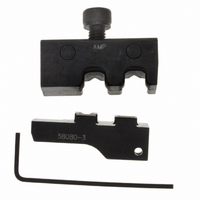
58080-3
Manufacturer Part Number
58080-3
Description
ULTRAFAST PLUS DIE SET 16-14 AWG
Manufacturer
Tyco Electronics
Series
Pro-Crimper III, Faston™, Plasti-Stripr
Type
Crimp Die Assemblyr
Specifications of 58080-3
Connector Type
Terminals and Splices
Crimp Handle
A28005-ND
Crimp Or Cable Size
14-16 AWG
Receptacles ,tyco Electronics / Amp
ROHS COMPLIANT
Product
Tool Component
Lead Free Status / RoHS Status
Not applicable / Not applicable
For Use With
A27852 - CONN FAST RECEPT 14-16 AWG .187A27856 - CONN FAST RECEPT 14-16 AWG .250A27850 - CONN FAST RECEPT 14-16 AWG .187
Lead Free Status / Rohs Status
Lead free / RoHS Compliant
Other names
58080-3
A28010
A28010


4. CRIMPING PROCEDURE
Select the appropriate wire size and terminal for the
die assembly. The wire size and insulation diameter
must be within a specified range for the terminal. Strip
the wire to the appropriate length shown in Figure 4.
Do NOT cut or nick the wire strands. Then, proceed
as follows:
2 of 4
3. Insert die retention screw through mounting hole
in top of tool frame and thread, but do not tighten,
the screw.
4. Carefully close the tool handles, making sure
that the dies align properly.
5. Tighten the die retention screw until secure.
1. Hold tool frame so that the FRONT side is
facing you and open crimping dies by squeezing
tool frame handles together until ratchet releases.
2. The locator stop must be adjusted to
accommodate the terminal series size, which is
marked on the terminal insulation (.187 or .250).
Rotate the blue plastic locator stop until the series
size number, appearing in the uppermost position,
matches the terminal series size. Refer to Figure 4.
3. Push the locator assembly away from the upper
crimping die slightly and hold.
Lower Jaw
Platform
Socket Head
Setscrew
Back Side of
Tool Frame
(Ref)
Figure 3
Die Retention Screw
5. MAINTENANCE AND INSPECTION
5.1. Maintenance
Hole Must Align
with Setscrew
4. Insert terminal mating end, flat side facing
locator, in the BACK side of the tool frame; center
on the appropriate crimping chamber on the lower
crimping die. Allow terminal to butt against locator
stop. See Figure 4.
5. Holding terminal in position, release locator
assembly. Insert stripped wire into wire barrel until
wire bottoms.
6. Hold wire in position and maintain light pressure.
Then, squeeze tool frame handles together until
ratchet releases.
7. Allow tool frame handles to open FULLY.
Holding locator assembly in position, remove
crimped terminal.
1. Remove dust, moisture and other contaminants
with a clean brush, or a soft, lint--free cloth. Do not
use objects that could damage the dies.
2. Make certain that all surfaces are protected with
a thin coat of any good SAE 20 motor oil. Do not
oil excessively.
3. When dies are not in use, store in a clean, dry
area.
Mounting Hole
Upper Jaw Platform
Die Assembly
Upper Die
Color Dot
Code
Lower Die
Color Dot
Code
408- 9278
Rev B