58079-3 Tyco Electronics, 58079-3 Datasheet - Page 3
58079-3
Manufacturer Part Number
58079-3
Description
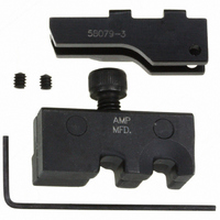
ULTRAFAST PLUS DIE SET 22-18 AWG
Manufacturer
Tyco Electronics
Series
Pro-Crimper III, Faston™, Plasti-Stripr
Type
Crimp Die Assemblyr
Specifications of 58079-3
Connector Type
Terminals and Splices
Crimp Handle
A28005-ND
Crimp Or Cable Size
18-22 AWG
Receptacles ,tyco Electronics / Amp
ROHS COMPLIANT
Fits Cable/wire
22-18 AWG
Product
Tool Component
Lead Free Status / RoHS Status
Not applicable / Not applicable
For Use With
A27854 - CONN FAST RECEPT 18-22 AWG .250A27848 - CONN FAST RECEPT 18-22 AWG .187A27846 - CONN FAST RECEPT 18-22 AWG .187
Lead Free Status / Rohs Status
Lead free / RoHS Compliant
Other names
58079-3
A28009
A28009


5.2. Periodic Inspection
Regular inspections should be performed with a
record of inspections remaining with the dies and/or
supervisory personnel responsible for them. TE
Connectivity recommends one inspection per month;
however, amount of use, working conditions, operator
training and skill, and established company standards
should determine frequency of inspection. The
inspection should be performed in the following
sequence:
A. Visual Inspection
B. Gaging the Crimping Chamber
This inspection requires the use of a plug gage
conforming to the diameters in Figure 5. TE does not
manufacture or market these gages. To gage the
crimping chambers, proceed as follows:
Rev B
NOTE: Not to Scale
1. Remove all lubrication and accumulated film by
immersing the dies in a suitable commercial
degreaser that will not affect paint or plastic
material.
2. Make sure the die retention screw and die
components are in place and secured. Refer to
Section 6, REPLACEMENT AND REPAIR, if
replacements are necessary.
3. Check all bearing surfaces for wear. Replace
worn components.
4. Inspect the crimping chambers for flattened,
chipped, cracked, worn, or broken areas. If
damage is evident, the dies must be repaired
before returning them to service. See Section 6,
REPLACEMENT AND REPAIR.
Strip Length
7.14 [.281]
Flat Side of
Terminal
Mating End
of Terminal
Insulation Barrel
Locator
Wire Barrel
Figure 4
GO DIM.
PART NO.
58079--3
58080--3
1. Remove traces of oil or dirt from the crimping
chambers and plug gage.
GO element must pass
completely through the
die closure.
DIE ASSEMBLY
GO Element
WIRE SIZE
MARKING
Suggested Plug Gage Design
22--20
Crimping
Chamber
18
16
14
Figure 5
[.0620--.0623]
[.0670--.0673]
Front Side of
Tool Frame (Ref)
[.0720--.0723]
[.0770--.0773]
1.575--1.582
1.702--1.709
1.829--1.836
1.956--1.963
Crimping Chamber
ELEMENT DIAMETER
GO
NO--GO element may enter
partially, but must not pass
completely through the
die closure.
Locator Stop
NO- - GO Element
[.0779--.0780]
[.0829--.0830]
[.0679--.0680]
[.0729--.0730]
1.979--1.981
2.106--2.108
NO--GO DIM.
1.725--1.727
1.852--1.854
NO- - GO
408- 9278
3 of 4