318452-2 Tyco Electronics, 318452-2 Datasheet - Page 4
318452-2
Manufacturer Part Number
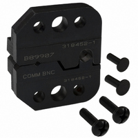
318452-2
Description
PROCRIMP DIE ASSY COMM BNC
Manufacturer
Tyco Electronics
Type
Dier
Specifications of 318452-2
Connector Type
BNC
Crimp Handle
Tyco/AMP 318452-1
Crimp Or Cable Size
Belden 9907, 89907, Comm/Scope 2104
Product
Tool Component
Description/function
BNC O Crimp Commercial
Features
Die for Pro-Crimper
Lead Free Status / RoHS Status
Not applicable / Not applicable
For Use With
50 Ohm RF Connectors
Other names
A24781


This inspection requires the use of a micrometer with
a modified anvil as shown in Figure 5.
Proceed as follows to check the crimp height of the
center contact:
This inspection requires the use of a plug gage
conforming to the dimensions in Figure 6. Tyco
Electronics does not manufacture or market these
gages. To gage the ferrule crimping chamber,
proceed as follows:
Measuring Center Contact Crimp Height
1. Select the center contact for the connector.
2. Refer to Section 4, CRIMPING PROCEDURE,
and crimp the center contact accordingly.
3. Using a crimp height comparator, measure the
crimp height as shown in Figure 5. If the crimp
height conforms to that shown, the die assembly is
considered dimensionally correct. If not, return the
dies to Tyco Electronics for evaluation and repair
(refer to Section 8, DIE REPLACEMENT).
1. Close the jaws until the dies have bottomed,
then HOLD the frame handles in this position. Do
NOT force the dies beyond initial contact.
2. Align the GO element with the ferrule crimping
chamber. Push the element straight into the
i
Tyco Electronics does not manufacture or market
these gages. However TE recommends the
modified micrometer (Crimp Height Comparator
RS-1019-5LP) or the digital Mitutoyo
micrometer.
Figure 5
If the crimping chamber conforms to the gage
inspection, the dies are considered dimensionally
correct, and should be lubricated with a THIN coat of
any good SAE 20 motor oil. If not, the dies must be
replaced before returning the die assembly to service
(see Section 8, DIE REPLACEMENT).
For additional information regarding the use of a plug
gage, refer to 408–7424.
The frame assembly ratchet mechanism features an
adjustment wheel with numbered settings. If the crimp
height is not acceptable, adjust the ratchet as follows:
Suggested Plug Gage for
Ferrule Crimping Chamber
crimping chamber without using force. The GO
element must pass completely through the
crimping chamber.
3. Align the NO–GO element and try to insert it
straight into the same crimping chamber. The
NO–GO element may start entry, but must not
pass completely through.
4. Repeat Steps 2 and 3 for the insulation ferrule
section of the crimping chamber.
1. Remove the lockscrew from the ratchet
adjustment wheel.
2. With a screwdriver, adjust the ratchet wheel
from the opposite side of the frame.
i
Insert the gage element for the insulation ferrule
section into the back of the crimping chamber.
The GO element for this section will not pass
completely through the crimping chamber.
Figure 6