91904-1 Tyco Electronics, 91904-1 Datasheet - Page 2
91904-1
Manufacturer Part Number
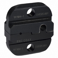
91904-1
Description
TOOL DIE SET SDE PREMIUM RG-187
Manufacturer
Tyco Electronics
Series
Coaxicon™r
Type
Crimp Die Assemblyr
Datasheet
1.91904-4.pdf
(5 pages)
Specifications of 91904-1
Connector Type
BNC
Crimp Handle
A9996-ND
Crimp Or Cable Size
RG/U-187
Product
Tool Component
For Use With
225791-6 - CONN SOCKET CONTACT COAX SIZE5225790-3 - CONN PIN CONTACT COAX SIZE5
Lead Free Status / RoHS Status
Not applicable / Not applicable
Lead Free Status / RoHS Status
na, Not applicable / Not applicable
Other names
A29143


4.2. Crimping the Ferrule
Rev C
Anvil Die
3. Holding the cable in place, close the tool handles
until the ratchet releases.
4. Allow the tool handles to open fully and remove
the crimped center contact from the dies.
1. Insert the crimped center contact into the
connector body until the cable dielectric butts
against the dielectric inside the connector body or
until the center contact is securely positioned within
the connector. Make sure that the braided shield is
over the support sleeve of the connector body and
that no strands from the shield enter the connector
body.
2. Slide the ferrule up over the braided shield and
onto the connector until the ferrule butts against the
shoulder on the connector body.
3. Place the ferrule in the appropriate crimping
chamber of the anvil die so that the shoulder on the
connector body butts against the edge of the die.
4. With a screwdriver, adjust the ratchet wheel from
the opposite side of the tool.
Crimping the Center Contact
NOTE
i
Refer to the instruction sheet packaged with the
connector to determine the appropriate crimping
chamber for the ferrule.
(Figure 3)
NOTE: Typical Crimping Dies Shown
Stripped
Cable
Figure 2
Shoulder on
Connector Body
Butts Against
Edge of Die
Typical Plug
Contact
Crimping the Ferrule
Ferrule in Crimping
Chamber on Anvil
Die
CAUTION
5. Carefully close the tool handles until the ratchet
releases.
Typical Jack
Contact
!
NOTE: Typical Crimping Dies Shown
Make sure that both sides of the ferrule are started
evenly into the crimping chamber. Do not attempt to
crimp an improperly positioned ferrule.
Figure 3
Crimping Die
Crimping Die
Flange on End of
Contact
Flange on End of
Contact
408-8579
2 of 5