58442-1 Tyco Electronics, 58442-1 Datasheet

TOOL HEAD ASSEMBLY RCPT MTA 100

58442-1

Manufacturer Part Number
58442-1
Description
TOOL HEAD ASSEMBLY RCPT MTA 100
Manufacturer
Tyco Electronics
Series
MTA-100r
Type
Hand Toolr
Datasheets

Specifications of 58442-1

Crimp Application
Connectors
Product
Crimping, Stripping & Cutting Tools & Drills
Description/function
Crimp tool assembly for discrete wire MTA-100 receptacles
For Use With
MTA-100 Feed-Through Receptacles
Lead Free Status / RoHS Status
Not applicable / Not applicable
Lead Free Status / RoHS Status
na, Not applicable / Not applicable
Other names
58442-1
A9973
1. INTRODUCTION
This instruction sheet covers operation and
maintenance of Terminating Head 58442–1 for use in
Electric Power Unit 931800–1, Pistol Grip Pneumatic
Handle Assembly 58075–1, or the Bench–Mount
Power Assembly 58338–1. Read these instructions
thoroughly before using the head.
For head installation and removal procedures, refer
to:
Reasons for reissue of this instruction sheet are
provided in Section 8, REVISION SUMMARY.
E
All International Rights Reserved
AMP and Tyco are trademarks. *Trademark
Other products, logos, and company names used are the property of their respective owners.
CAUTION
2003 Tyco Electronics Corporation, Harrisburg, PA
Wire Sub–Assembly
Retainer
NOTE
S
S
S
408–6789 (Pistol Grip Pneumatic Handle
Assembly 58075–1)
408–9393 (Bench–Mount Power Assembly
58338–1)
409–5746 (Electric Power Unit 931800–1)
Dimensions in this instruction sheet are in metric
units [with U.S. customary units in brackets].
Figures are for reference only and are not drawn
to scale.
Feed–Through Head 58442–1 was designed for
prototype cable assemblies, repair of cable
assemblies, and as an engineering tool. This
head was not designed for production type
environments.
Insert Housing
This controlled document is subject to change.
For latest revision, call the FAX/PRODUCT INFO number.
Feed–Through Pistol Grip
Terminating Head Assembly 58442–1
for Discrete MTA–.100 Connectors
Feed
Slide
Locating
Pawl
Figure 1
Wire Inserter
(Not Shown)
2. DESCRIPTION
Feed–Through Head 58442–1 is used to terminate 22
to 28 AWG wires in MTA–100 Receptacles 640620
and 640623. Refer to Catalog 82056 for connector
information. Slotted contacts for insulation displace-
ment termination are located on .100–in. centerlines.
Housings are color–coded to correspond with specific
wire sizes.
The head, which is inserted into an electric power as-
sembly or bench–mount power assembly, serves as a
guide and support for the connector during termina-
tion. Features of the head (shown in Figure 1) and
functions are as follows:
Wire inserter —forces wire into the two slotted beams
of the contact. Note that it provides support for the
contact beams when applying insertion force on the
wire.
Adjuster (insertion rod) —is a piston for the wire
inserter and regulates wire inserter travel.
Feed slide —automatically positions the connector
after each termination.
Locating pawl —aligns the connector for insertion, and
retains it during termination. The locating pawl is
sometimes referred to as the “anti–backup pawl.”
~
TOOLING ASSISTANCE CENTER 1–800–722–1111
FAX/PRODUCT INFO 1–800–522–6752
For Regional Customer Service, visit our website at
www.tycoelectronics.com
Instruction Sheet
408–9603
16 JUL 03 Rev A
Adjuster (Insertion
Rod) For Setting
Wire Inserter
Adjustment
(was IS 9603)
1 of 4
LOC B

58442-1 Summary of contents

Page 1

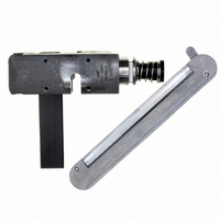
... Wire Sub–Assembly Retainer 1. INTRODUCTION This instruction sheet covers operation and maintenance of Terminating Head 58442–1 for use in Electric Power Unit 931800–1, Pistol Grip Pneumatic Handle Assembly 58075–1, or the Bench–Mount Power Assembly 58338–1. Read these instructions thoroughly before using the head. ...

Page 2

... Push the connector out of the right side of the head. 5. Inspect termination in accordance with Section 5, INSPECTION, Steps 1 through 6. If the wire is inserted too deeply, refer to the proce- dure in Paragraph 3.3, Wire Insertion Depth Adjustment MTA Terminating Head 58442–1 Production Connector Contact (Partially Removed) Contact Slot Lead–In ...

Page 3

... Left Side of Head Pneumatic Pistol Grip Handle Assembly Rev A MTA Terminating Head 58442–1 1. Insert connector into left side of head as shown in Figure 4. 2. Align the contact to be terminated with the wire inserter sure the locating pawl rests between the connector index ribs. ...

Page 4

... If damage is evident, repair is necessary. See Section 7, REPAIR. 7. REPAIR AND REPLACEMENT Customer–replaceable parts are listed on customer drawing 58442. A complete inventory should be stocked and controlled to prevent lost time when replacement of parts is necessary. Parts other than those listed should be replaced by Tyco Electronics to ensure quality and reliability ...