91901-1 Tyco Electronics, 91901-1 Datasheet - Page 2
91901-1
Manufacturer Part Number
91901-1
Description
TOOL DIE ASSEMBLY
Manufacturer
Tyco Electronics
Series
Certi-Crimper™r
Type
Crimp Die Assemblyr
Specifications of 91901-1
Connector Type
BNC
Crimp Handle
A9996-ND
Crimp Or Cable Size
RG/U-55B
Product
Tool Component
For Use With
BNC RG 55B
Lead Free Status / RoHS Status
Not applicable / Not applicable
Lead Free Status / RoHS Status
na, Not applicable / Not applicable
Other names
Q1851413


4.2. Crimping the Ferrule
2 of 4
Crimping the
Center Contact
CAUTION
CAUTION
Anvil Die
1. Insert the crimped center contact into the
connector body until the cable dielectric butts
against the dielectric inside the connector body or
until the center contact is securely positioned
within the connector. Make sure that the braided
shield is over the support sleeve of the connector
body and that no strands from the shield enter the
connector body.
2. Slide the ferrule up over the braided shield and
onto the connector until the ferrule butts against
the shoulder on the connector body.
3. Place the ferrule in the appropriate crimping
chamber of the anvil die so that the shoulder on
the connector body butts against the edge of the
die.
NOTE
4. With a screwdriver, adjust the ratchet wheel
from the opposite side of the tool.
5. Carefully close the tool handles until the ratchet
releases.
6. Allow the tool handles to open fully and remove
the crimped connector from the dies.
Refer to the instruction sheet packaged with the
connector to determine the appropriate crimping
chamber for the ferrule.
Make sure that both sides of the ferrule are
started evenly into the crimping chamber. Do
NOT attempt to crimp an improperly positioned
ferrule.
Damaged product should not be used. If a
damaged contact or ferrule is evident, it should
be replaced with a new one.
(Figure 3)
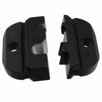
SDE Crimping Die Assemblies
NOTE: Typical Crimping Dies Shown
Stripped
Cable
Figure 2
5. CRIMP HEIGHT ADJUSTMENT
The tool frame assembly ratchet mechanism features
an adjustment wheel with numbered settings. If the
crimp height is not acceptable, adjust the ratchet as
follows:
Crimping the Ferrule
1. Remove the lockscrew from the ratchet
adjustment wheel.
2. With a screwdriver, adjust the ratchet wheel
from the opposite side of the tool.
Shoulder on
Connector Body
Butts Against
Edge of Die
Ferrule in
Crimping
Chamber on
Anvil Die
Typical Plug
Contact
Typical Jack
Contact
NOTE: Typical Crimping Dies Shown
Cross–Sectional View
Figure 3
(Figure 4)
Flange on End
of Contact
Flange on End
of Contact
Crimping
Die
Crimping
Die
408–8579
Rev B