575938 Tyco Electronics, 575938 Datasheet
575938
Manufacturer Part Number
575938
Description
TOOL HAND CRIMPING MATE-N-LOK
Manufacturer
Tyco Electronics
Series
Mate-N-Lokr
Specifications of 575938
Crimp Application
Mate-N-Lok Terminals
External Length / Height
285mm
Wire Area Size Max
2.5mm2
Wire Area Size Min
1mm2
Lead Free Status / RoHS Status
Not applicable / Not applicable
Features
-
For Use With/related Products
-
Tool Type
-
Lead Free Status / RoHS Status
na, Not applicable / Not applicable


1. INTRODUCTION
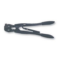
Crimping tools 575937 and 575938 (See Figure 1) are
used to crimp the MATE–N–LOK Terminals listed in
PROPER USE GUIDELINES
Cumulative Trauma Disorders can result from the prolonged use of manually powered hand tools. Hand tools are intended for occasional use and low volume
applications. A wide selection of powered application equipment for extended–use, production operations is available.
E
All International Rights Reserved
AMP and Tyco are trademarks. *Trademark
Other products, logos, and company names used are the property of their respective owners.
2003 Tyco Electronics Corporation, Harrisburg, PA
TOOL NUMBER
Pin
575937
575938
93
93
93
93
Locator Slot
TYPE “F”
A
B
CRIMP SYMBOL
Figure 1
A
A
B
A
A
B
This controlled document is subject to change.
For latest revision, call the FAX/PRODUCT INFO number.
Crimp Symbol
Stamped Here
CERTI–CRIMP*
Ratchet
MATE–N–LOK* Terminal
Crimping Tools
Insulation
Crimping
Adjustment
Pin in No. 3
Position
1000–2000 CMA
2000–3000 CMA
3
3000–5000 CMA
000–1500 CMA
0.3–0.75 mm
5.2 [.205]
0.5–1.0 mm
1.0–1.5 mm
1.5–2.5 mm
WIRE SIZE
3
C A
C A
C A
C A
Figure 2
the table in Figure 2. Use Figure 2 to select the
proper tool for the wire size to be used.
Reasons for reissue are provided in Section 5,
REVISION SUMMARY.
2. WIRE STRIPPING
Strip the wire 5.2 [.200] for both the pin and socket
terminals.
3. INSULATION CRIMPING ADJUSTMENT
INSULATION DIA.
NOTE
1. The insulation crimping jaws have three
adjustments.
2. Place the insulation crimping adjustment pin in
the No. 3 position. See Figure 1.
3. Place the terminal in the tool according to
Paragraph 4, and insert the unstripped wire into
only the insulation barrel.
4. Crimp the terminal. Bend the wire back and forth
once. If the wire pulls out, set pin in No. 2 position
and repeat the test until the desired grip is
obtained.
[.055–.100]
[.090–.130]
[.065–.110]
[.110–.150]
1.39–2.54
1.65–2.79
Socket
2.28–3.3
2.54–3.8
9
3
Wire Barrel
Dimensions in this instruction sheet are in
millimeters [with inches in brackets]. Figures are
for reference only and are not drawn to scale.
TOOLING ASSISTANCE CENTER 1–800–722–1111
FAX/PRODUCT INFO 1–800–522–6752
For Regional Customer Service, visit our website at
www.tycoelectronics.com
TERMINAL NO.
163240
163241
160495
160496
160497
160498
160497
160498
Insulation Barrel
TERMINAL H.P. NO.
Instruction Sheet
411–1040
07 OCT 03 Rev A
5.2 [.205]
163242
163243
160565
160566
160567
160568
160567
160568
(was IS 1040 GB)
1 of 2
LOC B
575938 Summary of contents
Page 1
... A wide selection of powered application equipment for extended–use, production operations is available TYPE “F” Figure 1 1. INTRODUCTION Crimping tools 575937 and 575938 (See Figure 1) are used to crimp the MATE–N–LOK Terminals listed in Locator Slot Pin TOOL NUMBER CRIMP SYMBOL ...
Page 2
... CRIMPING PROCEDURE 1. These tools is equipped with a CERTI–CRIMP Ratchet (see Figure 1) to ensure proper crimping. To open the tool handles, squeeze them until the ratchet releases. Once the ratchet is engaged, the handles cannot NOTE be opened until they are fully closed. 2. Place the terminal in the tool so that the locator fits in the slot between the terminal insulation barrel and the wire barrel ...