170-701-170-000 Norcomp Inc., 170-701-170-000 Datasheet - Page 2
170-701-170-000
Manufacturer Part Number
170-701-170-000
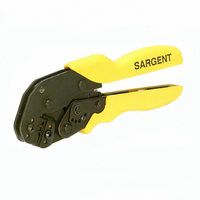
Description
TOOL HAND CRIMP STAMPED CONTACTS
Manufacturer
Norcomp Inc.
Series
170r
Datasheet
1.170-701-170-000.pdf
(3 pages)
Specifications of 170-701-170-000
Tool Type
Hand Crimper
Features
Side Entry, Ratchet
For Use With/related Products
D-Sub Contacts, 24-28 AWG
For Use With
86SE - CONN SKT STAMPED 24-28AWG 10GOLD85SE - CONN SOCKT STAMPED 24-28AWG GOLD84PE - CONN PIN STAMPED 24-28AWG 10GOLD83PE - CONN PIN STAMPED 24-28AWG GOLD82SECT - CONTACT FEMALE 24-28AWG 10GOLD82SSFECT - CONTACT FEMAL 24-28AWG GOLD FLSH82PECT - CONTACT MALE 24-28AWG 10GOLD82PSFECT - CONTACT MALE 24-28AWG GOLD FLASH82SETR - CONTACT FEMALE 24-28AWG 10GOLD82SSFETR - CONTACT FEMAL 24-28AWG GOLD FLSH82PETR - CONTACT MALE 24-28AWG 10GOLD82PSFETR - CONTACT MALE 24-28AWG GOLD FLASH
Lead Free Status / RoHS Status
Not applicable / Not applicable
Other names
170701170000
T1000S
T1000S


3. CRIMPING PROCEDURE
Strip the wire to the length indicated, taking care not
to nick or cut the wire strands. Select an applicable
contact and identify the appropriate crimping
chamber according to the wire size (24-28) markings
on the tool.
Refer to Figure 2, and proceed as follows:
CAUTION
NorComp, Inc.
Charlotte, NC
1. Hold the tool so that the front is facing you.
2. Insert the contact (mating end first) into the
3. Hold the contact in position, and squeeze
4. Insert stripped wire into contact insulation
Contact Wire
Locator in
Squeeze tool handles together and allow
them to open fully.
hole in the locator which corresponds with
the appropriate crimping chamber.
sure that the open “U” of the wire barrel and
insulation barrel face the stationary jaw.
the tool handles together until ratchet
engages sufficiently to hold the contact in
position. Do NOT deform insulation barrel
or wire barrel.
and wire barrels until wire and insulation are
visible in inspection window, as shown in
Figure 2.
Stop Slot
Make sure that both sides of the
contact insulation barrel are started
evenly into the crimping chamber.
Do NOT attempt to crimp an
improperly positioned contact.
Figure 2
Stationary
Tool
Jaw
Wire Inserted
to Locator
Wire Stop
Wire Strip
Length
This document is subject to change
Make
Rev 1
170-701-170-000
11-23-09
4. CRIMP PULL TEST
5. CRIMP ADJUSTMENT
6. DAILY MAINTENANCE
5. Holding the wire in place, squeeze the tool
1. Refer
1. See Manufacturers data sheet (GMT-DS)
Properly crimped terminals are controlled by the
following
procedures.
1. Clean all dust, dirt, moisture and other
2. The pivot pin and ratcheted pawl-bearing
3. When storing the tool, close the handles
DO NOT immerse tool in cleaning solution
handles together until ratchet releases.
Allow tool handles to open and remove
crimped contact.
PROCEDURE,
accordingly to achieve pull test in Figure 3.
supplied with hand tool.
foreign matter from the crimp jaws that could
damage the crimp area of the dies.
surface should be lubricated to ensure a
smooth operation.
until the ratchet pawl is about to be released
from the tooth of the ratchet. This will help
prevent the dies from being damaged.
DO NOT spray oil into tool to lubricate
WIRE SIZE
Max AWG
28
26
24
maintenance
to
Figure 3
Section
and
Date Printed 11/24/2009
crimp
and
TEST PULL
3,
Instruction Sheet
lb.
the
4
6
8
Page 2 of 3
CRIMPING
inspection
IS-170S
contact