64001-2800 Molex Inc, 64001-2800 Datasheet - Page 2
64001-2800
Manufacturer Part Number
64001-2800
Description
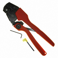
TOOL CRIMP FLAG QD .250 10-12AWG
Manufacturer
Molex Inc
Series
Avikrimp®, Insulkrimp®r
Specifications of 64001-2800
Features
Side Entry, Ratchet
Tool Type
Hand Crimper
Fits Cable/wire
12-10 AWG
Lead Free Status / RoHS Status
Not applicable / Not applicable
For Use With/related Products
Quick Connects Terminals, 10-12 AWG
For Use With
WM2944 - CONN RCPT FLAG 10-12AWG .250 YLWWM18249 - CONN .250" FLAG INSUL 10-12AWGWM18244 - CONN .250" FLAG INSUL 10-12AWG
Lead Free Status / Rohs Status
Lead free / RoHS Compliant
Other names
064001-2800
064001-2800-P
0640012800
0640012800-P
64001-2800-P
640012800
640012800-P
WM18589
064001-2800-P
0640012800
0640012800-P
64001-2800-P
640012800
640012800-P
WM18589


RHT 64001-2800 Hand Crimp Tool
OPERATION
Open the tool by first closing the jaws sufficiently for the ratchet
mechanism to release.
Crimping Terminals
Doc No. ATS-640012800 Release Date: 05-30-03
Revision: E
1. Insert the terminal with the barrel into the color-coded nest
2. Partially close the tool to hold the terminal in place shown in Figure 2.
3. Insert the properly stripped wire into the terminal barrel. See Figure 2 and 3. The wire ends
4. Remove the crimped terminal. Inspect for proper crimp location, and check for insulation
5. If the insulation part of the crimp needs to be adjusted, first loosen the M4 screw on the bottom
and the square edge of the flag facing out. Make sure the
back of the flag terminal is against the locator. See Figure
1. If terminal is not flush against the locator loosen the M4
wing nut and adjust the locator up or down so that the flat
edge of the terminal is flush against the wall of the locator. Tighten the M4 wing nut. See
Figure 3.
should butt against the inside of the connector. Cycle the tool.
Note: The tamper proof ratchet action will not release the tool until it has been fully
closed.
closure.
tool jaw, then insert a 3/32 hex wrench (supplied) into the bottom of the lower die. See Figure 4.
A clockwise (CW) rotation decreases insulation crimp while a counter-clockwise (CCW) rotation
increases insulation crimp. After adjusting, retighten the M4 screw.
TERMINAL
Figure 2
Revision Date: 12-06-06
WIRE
UNCONTROLLED COPY
M4 WING NUT
FLAT EDGE OF
LOCATOR
TERMINAL
CONDUCTOR
CONDUCTOR
PUNCH
ANVIL
JAWS OPEN
LOCATOR
Figure 3
Figure 1
INSULATION
INSULATION
ANVIL
PUNCH
TERMINAL
BARREL
TERMINAL
WIRE
Page 2 of 7