90800-1 Tyco Electronics, 90800-1 Datasheet - Page 2
90800-1
Manufacturer Part Number
90800-1
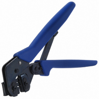
Description
TOOL CRIMP HI-DEN D-SUB W/DIE
Manufacturer
Tyco Electronics
Series
Pro-Crimper™ III, AMPLIMITE®r
Type
Crimpersr
Specifications of 90800-1
Tool Type
Hand Crimper
Features
Side Entry, Ratchet
Rohs Compliant
NA
Product
Crimping, Stripping & Cutting Tools & Drills
Lead Free Status / RoHS Status
Not applicable / Not applicable
For Use With/related Products
D-Sub Contacts, 22-28 AWG
For Use With
1658670-5 - CONN PIN 22-28AWG CRIMP 30GOLDA31956 - CONN D-SUB SOCKET 22-28AWG GOLDA31955 - CONN D-SUB SOCKET 22-28AWG GOLDA31954 - CONN D-SUB PIN 22-28AWG GOLDA31953 - CONN D-SUB PIN 22-28AWG GOLD
Lead Free Status / Rohs Status
Lead free / RoHS Compliant
Other names
A9815


When closed, the dies form two crimping chambers.
Each die is held in the tool frame by a retaining screw
and two retaining pins.
3. INSTALLATION AND REMOVAL OF DIE ASSEMBLY
AND LOCATOR ASSEMBLY
Rev D
1. Close the tool handles until the ratchet releases,
then allow the handles to open fully.
2. Remove the two die retaining screws from the
tool jaws.
3. Slide the wire anvil and insulation anvil dies onto
the moving jaw so that the chamfers and marked
surfaces face outward as shown in Figure 2, then
insert the two die retaining pins through the holes in
the moving jaw and into the holes in the dies.
4. Thread, but do not tighten, the short die retaining
screws through the holes of the moving jaw and into
the holes in both anvil dies.
5. Slide the wire crimper and insulation crimper dies
onto the stationary jaw so that the chamfers and
marked surfaces face outward as shown in Figure 2,
then insert the two die retaining pins through the holes
in the stationary jaw and into the holes in the dies.
6. Thread, but do not tighten, the long die retaining
screws through the holes of the moving jaw and into
the holes in both crimper dies.
7. Carefully close the tool handles, making sure that
the dies align properly. Continue closing the
handles until the ratchet has engaged sufficiently to
hold the dies in place.
8. Tighten the die retaining screws using the
appropriate screwdriver.
Chamfer
Wire Anvil
Die
Offset
Nut
Wire Crimper
Die
Locator
Insulation
Crimper
Die
Chamfer
Insulation Anvil
Die
Locator Assembly
Figure 2
4. CRIMPING PROCEDURE
Refer to Figure 1, and select wire of the specified size
and insulation diameter. Strip the wire to the
dimension given in Figure 1, taking care not to nick or
cut wire strands. Then proceed as follows:
9. Place the locator assembly over the end of the
long die retaining screw, and position the locator
assembly against the side of the tool jaw.
10. Place the nut onto the end of the long die
retaining screw, and tighten the nut enough to hold
the locator assembly in place, while still allowing the
locator to slide up and down.
11. To disassemble, close the tool handles until the
ratchet releases. Remove the nut, locator assembly,
the two die retaining screws, and four die retaining
pins, then, slide the dies out of the tool jaws.
1. Hold the tool so that the back (wire side) faces
you. Close the tool handles until the ratchet
releases, then allow the handles to open FULLY.
2. Insert the contact (insulation barrel first) into the
front of the appropriate crimping chamber (refer to
the markings on the die).
3. Position the contact so that the mating end is on
the locator side of the tool frame and the open “U” of
the wire barrel and insulation barrel faces the top of
NOTE
Short Die Retaining
Screw
i
Tool Jaws
The tool frame is provided with a crimp adjustment
feature. Initially, the crimp height should be verified
according to Section 6, CRIMP HEIGHT
INSPECTION, and if necessary, adjusted
according to Section 7, CRIMP HEIGHT
ADJUSTMENT before using the tool.
Die Retaining Pin
(4 Places)
Long Die Retaining
Screw
408-4007
2 of 5