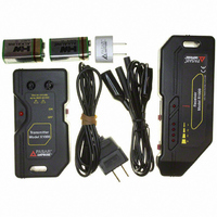
AT-1000 Amprobe, AT-1000 Datasheet

AT-1000
Specifications of AT-1000
705-1018
AT-1000 Summary of contents
Page 1
... Users Manual AT-1000 Advanced Wire Tracer ...
Page 2
... AT-1000 Advanced Wire Tracer Users Manual AT1000_Rev001 © 2008 Amprobe Test Tools. All rights reserved. ...
Page 3
... MAnUfACTUReR ShAll noT be liAble foR AnY SpeCiAl, indiReCT, inCidenTAl oR ConSeqUenTiAl dAMAgeS oR loSSeS, ARiSing fRoM AnY CAUSe oR TheoRY. Since some states or countries do not allow the exclusion or limitation of an implied warranty or of incidental or consequential damages, this limitation of liability may not apply to you ...
Page 4
R1000 Receiver 3 x1000 Transmitter ...
Page 5
... CoNTENTS Symbols .................................................................................................................................................... 5 introduction ............................................................................................................................................. 5 Safety precautions and Warnings .......................................................................................................... 5 Unpacking and inspection ...................................................................................................................... 6 Component description .......................................................................................................................... 6 R1000 Receiver ................................................................................................................................... 6 x1000 Transmitter .............................................................................................................................. 6 Replacing batteries: R1000 and x1000 .................................................................................................. 7 operation ................................................................................................................................................ 7 Tracing energized Wires ......................................................................................................................... 7 locating opens ........................................................................................................................................ 8 locating Shorts ........................................................................................................................................ 8 fuse Replacement ................................................................................................................................... 8 Specifications ........................................................................................................................................... 9 Advanced Wire Tracer 4 AT-1000 ...
Page 6
... AMpRobe has a history of providing safe, reliable equipment to trace energized wires, circuit breakers, tracing deenergized wires, and locating opens. The AT-1000 Advanced Tracing System combines these features in one versatile tool and is effective in solving most tracing problems. The AT-1000 is a troubleshooting tool. An experienced troubleshooter will understand how the system to be traced works under normal conditions, and be familiar with the types of malfunctions that can exists. A thorough understanding of “ ...
Page 7
... This is particularly evident when the R1000 is in the “CURRenT” Mode. pointing the receiver perpendicular to the wire, so that the front label faces the direction of the wire, will yield the maximum signal displayed. AT-1000E (Europe version R1000 Receiver 1 x x1000 Transmitter ...
Page 8
... When connected to an open circuit, the x1000 will inject a 17khz voltage fluctuation that can be detected, by the R1000 in the “open” mode, along the circuit path to the end of that circuit. proper operation of the x1000 Transmitter is confirmed when the R1000 received indicates a pulsed signal ...
Page 9
... R1000 left to right over the path of the wire so that you can see the rise and fall of the signal level (see fig. 7). The strongest signal confirms the path of the wire. if the signal drops off, the wire may have taken a turn in another direction. ...
Page 10
... R1000 left to right over the path of the wire so that you can see the rise and fall of the signal level (see fig. 7). Adjust the “Sensitivity Range Switch” to display 3 led’s of signal strength. The strongest signal confirms the path of the wire ...
Page 11
... Replacement fig. 2a: C2901 Cordset fig. 3: eU-200 Cordset fig. 2b: C2902 Cordset 10 ...
Page 12
... Signal Attenuation 11 ...
Page 13
Tracing Conductors fig. 7: Tracing Wires 12 ...
Page 14
... Tracing opens fig. 9: locating Shorts 13 ...
Page 15
View fig. 10: fuse Replacement fig. 10b: x1000 with front Cover Removed 14 ...
Page 16
... Visit www.Amprobe.com for • Catalog • Application notes • product specifications • User manuals please Recycle ...


