FLUKE-52-2 60HZ Fluke Electronics, FLUKE-52-2 60HZ Datasheet
FLUKE-52-2 60HZ
Specifications of FLUKE-52-2 60HZ
52-2 60HZ
614-1034
674689


FLUKE-52-2 60HZ Summary of contents
Page 1
... English September 1999 Rev.1, 6/01 © 1999-2001 Fluke Corporation, All rights reserved. Printed in USA All product names are trademarks of their respective companies. 51 & 52 Series II ® Thermometer Users Manual ...
Page 2
... This Fluke product will be free from defects in material and workmanship for 3 years from the date of purchase. This war- ranty does not cover fuses, disposable batteries or damage from accident, neglect, misuse or abnormal conditions of opera- tion or handling. Resellers are not authorized to extend any other warranty on Fluke’s behalf. To obtain service during the warranty period, send your defective tester to the nearest Fluke Authorized Service Center with a description of the problem ...
Page 3
... Introduction .................................................................................................................... 1 Contacting Fluke ....................................................................................................... 1 Getting Started............................................................................................................... 4 Components.............................................................................................................. 5 Display Elements ...................................................................................................... 6 Buttons...................................................................................................................... 7 Using the Thermometer ................................................................................................. 9 Changing Setup Options................................................................................................ 9 Entering or Exiting Setup .......................................................................................... 9 Setup Options ........................................................................................................... 9 Changing a Setup Option.......................................................................................... 10 Measuring Temperatures............................................................................................... 11 Connecting a Thermocouple ..................................................................................... 11 Displaying Temperatures .......................................................................................... 11 Holding the Displayed Readings ............................................................................... 12 Viewing the MIN, MAX, and AVG Readings.............................................................. 12 Using the Offset to Adjust for Probe Errors.................................................................... 12 ...
Page 4
Series II Users Manual Maintenance................................................................................................................... 13 Replacing the Batteries ............................................................................................. 13 Cleaning the Case and Holster.................................................................................. 13 Calibration ................................................................................................................. 13 Specifications ................................................................................................................. 13 Environmental............................................................................................................ 13 General...................................................................................................................... 14 80 PK-1 Thermocouple (supplied with thermometer) ................................................ 14 Electrical.................................................................................................................... 14 ...
Page 5
... Introduction The Fluke Model 51 and Model 52 Thermometers (“the thermometer”) are microprocessor-based, digital thermometers designed to use external J-, K-, T-, and E- type thermocouples (temperature probes) as temperature sensors. Use the thermometer only as specified in this manual. Otherwise, the protection provided by the meter may be impaired. Refer to safety information in Table 1 and meter symbols in Table 2. 51 & ...
Page 6
Series II Users Manual A Warning identifies conditions and actions that pose hazards to the user. To avoid electrical shock or personal injury, follow these guidelines: Before using the thermometer inspect the case. Do not use the ...
Page 7
Model 52: Measurement errors may occur if voltages on the measurement surfaces result in potentials greater than 1 V between the two thermocouples. When potential differences are anticipated between the thermocouples, use electrically insulated thermocouples. When servicing the thermometer, use ...
Page 8
Series II Users Manual W Refer to the manual for information about this feature. M Battery. Getting Started Everything in this Users Manual applies both to Models 51 and 52 unless otherwise indicated. To become familiar with ...
Page 9
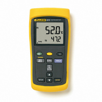
Components Figure 1. Components Table 3. Components xx Thermocouple T1 input Model 52: Thermocouple T2 input Holster 2 Display 1 Buttons Battery door Batteries aas01f.eps 51 & 52 Series II Getting Started 5 ...
Page 10
Series II Users Manual Display Elements Figure 2. Display Elements 6 xx The thermocouple measurement includes an offset. See "Changing Setup Options." The displayed readings do not change. A shift ...
Page 11
Buttons Press to turn the thermometer on or off. Press , (CANCEL) to stop displaying the minimum, maximum, and average readings in the secondary display. (Shift function) Press to turn the backlight on and off. The backlight turns off after ...
Page 12
Series II Users Manual Press to start or exit Setup. (See "Changing Setup Options.") Press to scroll to the Setup option you want to change. Press to increase the displayed setting. Press to scroll to the Setup ...
Page 13
Using the Thermometer 1. Plug the thermocouple(s) into the input connector(s). 2. Press to turn on the thermometer. After 1 second the thermometer displays the first reading thermocouple is plugged into the selected input or the thermocouple is ...
Page 14
Series II Users Manual Changing a Setup Option 1. Press or to scroll to the setup option you want to change. 2. Press to indicate that you want to change this setting. 3. Press or until the ...
Page 15
Measuring Temperatures Connecting a Thermocouple To change the thermocouple type, see “Changing Setup Options.” The North American ANSI Color Code is: Type Color Black Yellow Purple 1. Plug a thermocouple into the input connector(s). (Make sure that ...
Page 16
Series II Users Manual Holding the Displayed Readings 1. Press to freeze the readings on the display. The display shows . Model 52: Press 2. to toggle showing the T1, T2, or T1-T2 readings in the primary ...
Page 17
... To ensure that the thermometer performs to its accuracy specifications, Fluke recommends that you calibrate the thermometer annually, starting one year after purchase. To calibrate the thermometer, contact Fluke for the Service Center nearest you or follow the calibration procedure in the service manual listed in "Replacement Parts and Accessories." ...
Page 18
Series II Users Manual General Weight 280 g (10 oz) Dimensions 2.8 cm 7.8 cm (without (1 6.4 in) holster) Battery 3 AA batteries Certification Safety CSA C22.2 No. 1010.1 1992 ...
Page 19
Electrical (cont.) Measurement J-, K-, T-, and E-type: [0.05 o Accuracy, T1, reading 0.3 C (0.5 o T2, or T1-T2 [below 100 C ( 148 (Model 52) of reading for J-, K-, E-, and N-type; and 0. reading ...
Page 20
Series II Users Manual 16 ...