ACF-3000AK Amprobe, ACF-3000AK Datasheet - Page 10
ACF-3000AK
Manufacturer Part Number
ACF-3000AK
Description
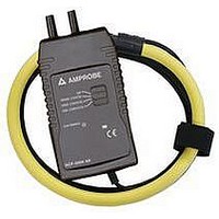
FLEX CURRNT TRANSDUCER 3000A
Manufacturer
Amprobe
Type
AC Clampr
Datasheet
1.ACF-3000AK.pdf
(63 pages)
Specifications of ACF-3000AK
Style
Flexible Ring
Ac Current Range
30 ~ 3000A
Bandwidth
20kHz
Cable Length
78.740" (2000.00mm)
Max Conductor Size
7.000" (177.80mm)
Termination
Banana Plug, Double, Sheathed
Ratings
CAT III 600V
Frequency Max
20kHz
Length
116mm
Frequency Min
10Hz
Operating Frequency Range
10Hz To 20kHz
Current Measuring Range
30A/300A/3000A
Frequency Measuring Range
10Hz To 20kHz
Accessory Type
AC Current Probe
Sensor Operating Frequency
10Hz To 20kHz
Rohs Compliant
NA
Accuracy
± 1% Of Range
Accuracy %
1%
Battery Size Code
AA
Lead Free Status / RoHS Status
Contains lead / RoHS compliant by exemption
For Use With
DMM, Oscilloscope, Recording Instruments
Lead Free Status / RoHS Status
na, Contains lead / RoHS compliant by exemption
Other names
2732388


4
4.1
4.2
OPERATION
BATTERY INSTALLATION
Never replace batteries with flexible measuring head installed on
conductor to be tested or output connected to a display device.
Never operate the unit without the battery cover fitted.
The Amprobe ACF3000 AK requires two AA MN1500 LR6 alkaline
batteries for operation. The battery compartment is accessed from the
rear of the electronics enclosure.
The batteries must be replaced when the LED is lit continuously or fails to
light up. Ensure that the Amprobe ACF3000 AK current probe is away
from any current carrying conductor and the output is disconnected from
any other equipment.
Using a coin or a similar tool turn the battery lock ¼ turn until the dot
aligns with the unlock symbol. The battery cover can now be removed.
Install the batteries ensuring that correct polarity is observed. Replace the
battery cover and turn the battery lock until the dot aligns with the lock
symbol.
MEASURING CURRENT WITH THE AMPROBE
ACF3000 AK
Read safety section of instructions before operating this product
Ensure conductor to be tested is de energised.
Connect the output of the electronics to the VOLTS input of the DMM or
other data recording device.
6
Operation