TR8M226M6R3C1500 Vishay, TR8M226M6R3C1500 Datasheet - Page 3
TR8M226M6R3C1500
Manufacturer Part Number
TR8M226M6R3C1500
Description
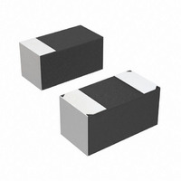
CAP TANT 22UF 6.3V 20% 0603
Manufacturer
Vishay
Series
MICROTAN™ TR8r
Type
Moldedr
Datasheet
1.TR8M105M016C9500.pdf
(9 pages)
Specifications of TR8M226M6R3C1500
Capacitance
22µF
Voltage - Rated
6.3V
Tolerance
±20%
Esr (equivalent Series Resistance)
1.500 Ohm
Operating Temperature
-55°C ~ 125°C
Mounting Type
Surface Mount
Package / Case
0603 (1608 Metric)
Size / Dimension
0.063" L x 0.033" W (1.60mm x 0.85mm)
Height
0.032" (0.80mm)
Manufacturer Size Code
M
Features
General Purpose
Voltage Rating
6.3 Volts
Operating Temperature Range
- 55 C to + 85 C
Dimensions
0.85 mm W x 1.6 mm L
Product
Tantalum Solid Low ESR Standard Grade
Termination Style
SMD/SMT
Lead Free Status / RoHS Status
Lead free / RoHS Compliant
Lead Spacing
-
Lead Free Status / Rohs Status
Details
Other names
718-1671-2


www.vishay.com
40
TR8
Vishay Sprague
CAPACITORS PERFORMANCE CHARACTERISTICS
Notes
• At + 25 °C, the leakage current shall not exceed the value listed in the Standard Ratings Table.
• At + 85 °C, the leakage current shall not exceed 10 times the value listed in the Standard Ratings Table.
• At + 125 °C, the leakage current shall not exceed 12 times the value listed in the Standard Ratings Table.
ELECTRICAL PERFORMANCE CHARACTERISTICS
ITEM
Category Temperature Range
Capacitance Tolerance
Dissipation Factor (at 120 Hz)
ESR (100 kHz)
Leakage Current
Reverse Voltage
Temperature Derating
Operating Temperature
TYPICAL LEAKAGE CURRENT FACTOR RANGE
PERFORMANCE CHARACTERISTICS
- 55 °C to + 85 °C (to + 125 °C with voltage derating)
± 20 %, ± 10 % (at 120 Hz) 2 V
Limits per Standard Ratings Table. Tested via bridge method, at 25 °C, 120 Hz.
Limits per Standard Ratings Table. Tested via bridge method, at 25 °C, 100 kHz.
After application of rated voltage applied to capacitors for 5 minutes using a steady source of power with
1 k resistor in series with the capacitor under test, leakage current at 25 °C is not more than described in.
See graph below for the appropriate adjustment factor.
Capacitors are capable of withstanding peak voltages in the reverse direction equal to: 10 % of the DC
5 % of the DC rating at + 85 °C
Vishay does not recommended intentional or repetitive application of reverse voltage
If capacitors are to be used at temperatures above + 25 °C, the permissible rms ripple current or voltage
1.0 at + 25 °C
0.9 at + 85 °C
WORKING VOLTAGE
M
0.001
ICRO
0.01
100
1.0
0.1
For technical questions, contact:
10
6.3
10
16
20
25
35
50
0
4
T
Solid Tantalum Chip Capacitors
AN
10
™ Low ESR, Leadframeless Molded
+ 85 °C RATING
20
PERCENT OF RATED VOLTAGE
30
SURGE VOLTAGE
rms
40
at + 25 °C using a capacitance bridge
50
5.2
13
20
26
32
46
65
8
tantalum@vishay.com
+ 125 °C
60
70
+ 85 °C
80
+ 55 °C
WORKING VOLTAGE
+ 25 °C
- 55 °C
90
0 °C
100
2.7
10
13
17
23
33
4
7
+ 125 °C RATING
Document Number: 40114
SURGE VOLTAGE
Revision: 14-Jan-11
3.4
12
16
20
28
40
5
8
Related parts for TR8M226M6R3C1500
Image
Part Number
Description
Manufacturer
Datasheet
Request
R

Part Number:
Description:
357-036-542-201 CARDEDGE 36POS DL .156 BLK LOPRO
Manufacturer:
Vishay
Datasheet:
Part Number:
Description:
357-036-542-201 CARDEDGE 36POS DL .156 BLK LOPRO
Manufacturer:
Vishay
Datasheet:
Part Number:
Description:
357-036-542-201 CARDEDGE 36POS DL .156 BLK LOPRO
Manufacturer:
Vishay
Datasheet:
Part Number:
Description:
357-036-542-201 CARDEDGE 36POS DL .156 BLK LOPRO
Manufacturer:
Vishay
Datasheet:
Part Number:
Description:
357-036-542-201 CARDEDGE 36POS DL .156 BLK LOPRO
Manufacturer:
Vishay
Datasheet:
Part Number:
Description:
357-036-542-201 CARDEDGE 36POS DL .156 BLK LOPRO
Manufacturer:
Vishay
Datasheet:
Part Number:
Description:
357-036-542-201 CARDEDGE 36POS DL .156 BLK LOPRO
Manufacturer:
Vishay
Datasheet:
Part Number:
Description:
357-036-542-201 CARDEDGE 36POS DL .156 BLK LOPRO
Manufacturer:
Vishay
Datasheet:
Part Number:
Description:
357-036-542-201 CARDEDGE 36POS DL .156 BLK LOPRO
Manufacturer:
Vishay
Datasheet:
Part Number:
Description:
357-036-542-201 CARDEDGE 36POS DL .156 BLK LOPRO
Manufacturer:
Vishay
Datasheet:
Part Number:
Description:
357-036-542-201 CARDEDGE 36POS DL .156 BLK LOPRO
Manufacturer:
Vishay
Datasheet:
Part Number:
Description:
357-036-542-201 CARDEDGE 36POS DL .156 BLK LOPRO
Manufacturer:
Vishay
Datasheet:
Part Number:
Description:
357-036-542-201 CARDEDGE 36POS DL .156 BLK LOPRO
Manufacturer:
Vishay
Datasheet:
Part Number:
Description:
357-036-542-201 CARDEDGE 36POS DL .156 BLK LOPRO
Manufacturer:
Vishay
Datasheet:
Part Number:
Description:
357-036-542-201 CARDEDGE 36POS DL .156 BLK LOPRO
Manufacturer:
Vishay
Datasheet: