DZ-2R5D665Z6T Elna America, DZ-2R5D665Z6T Datasheet - Page 141
DZ-2R5D665Z6T
Manufacturer Part Number
DZ-2R5D665Z6T
Description
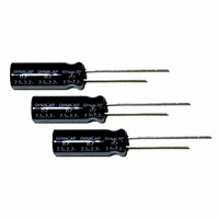
CAP DOUBLE LAYER 6.6F 2.5V RAD
Manufacturer
Elna America
Series
DZr
Specifications of DZ-2R5D665Z6T
Capacitance
6.6F
Voltage - Rated
2.5V
Tolerance
-20%, +80%
Esr (equivalent Series Resistance)
200.0 mOhm
Lifetime @ Temp.
1000 Hrs @ 70°C
Mounting Type
Through Hole
Package / Case
Radial, Can
Lead Spacing
0.197" (5.00mm)
Height
0.906" (23.00mm)
Size / Dimension
0.492" Dia (12.50mm)
Operating Temperature
-25°C ~ 70°C
Lead Free Status / RoHS Status
Lead free / RoHS Compliant


CAT.No.2008/2009E ( 2008.10.1 )
TECHNICAL NOTE
3 Calculation Method of Discharge Time
3-1 Approximating the Discharge Time of Basic
Constant Current Discharge
The discharge time at the constant current of a
capacitor can be calculated by the following
equation.
As an example, we calculate the discharge time when
a capacitor of the DB series 5.5V 1F is charged with
5V and discharged to 3V at a constant current of 1
mA. Since the working voltage range ΔV is 2V
from 5 − 3V, t = (1F × 2V)/0.001A from the above
equation, and the discharge time can be calculated
as 2,000 seconds (about 33 minutes). Note that
the actual discharge time may be different because
this equation does not cover the effect of the
self-discharge and the IR drop by internal resistance
described below.
3-2 Effect of Self-discharge at Microcurrents
When backup is made by discharge with a micro-
current below some µA especially for the memory
backup application and the like, the discharge time
must be determined while taking into account the self-
discharge as shown in Fig.4.
The value closer to the actual discharge curve is
obtained by adding the voltage drop through the self-
discharge determined from the voltage retention
characteristic test to the discharge curve given by
calculation.
Note that the value of self-discharge varies by
the charge time, charging current and an ambient
temperature.
Where,
t = (C×ΔV)/I
Fig.4 Example of Discharge Curve involving Self-Discharge
ΔV : Working voltage range (V)
C : Capacitor capacitance (F)
t : Discharge time (sec.)
I : Discharge current (A)
Actual discharge curve
Discharge curve given by calculation
Time
ELECTRIC DOUBLE
LAYER CAPACITORS
3-3 Effect of IR Drop at Large Currents
When a large Current discharge and a capacitor with
a high internal resistance are used, the effect of IR
drop by the product of the internal resistance and the
current must be considered as shown in Fig.5.
When a large current is required in a very short time,
or a large instantaneous current flows at the start of
discharge, the voltage drop indicated with ΔV1 counts.
However, when the discharge continues as it is, the
discharge curve indicates in a manner showing a slow
diffusion and then keeps a constant straight line.
We also make calculation including ΔV2 of the
intersection extending from the initial discharge and
the discharge straight line section including the
diffusion curve when indicating the DC internal
resistance.
Due to IR drop, the shape of the discharge curve
varies by the internal resistance and ambient
temperature for each series.
E
Fig.5 Example of Discharge Curve involving IR Drop
NOTE
Design, Specifications are subject to change without notice.
Ask factory for technical specifications before purchase and/or use.
Charge
V
2
Discharge
V
1
®
Related parts for DZ-2R5D665Z6T
Image
Part Number
Description
Manufacturer
Datasheet
Request
R

Part Number:
Description:
CAP DOUBLE LAYER .10F 5.5V COIN
Manufacturer:
Elna America
Datasheet:

Part Number:
Description:
Supercapacitors V/MOUNT 5.5V 0.1F
Manufacturer:
Elna America
Datasheet:

Part Number:
Description:
CAP DOUBLE LAYER .07F 3.3V COIN
Manufacturer:
Elna America
Datasheet:

Part Number:
Description:
CAP DOUBLE LAYER .20F 3.3V COIN
Manufacturer:
Elna America
Datasheet:

Part Number:
Description:
CAP DOUBLE LAYER .22F 3.3V COIN
Manufacturer:
Elna America
Datasheet:
Part Number:
Description:
CAP DOUBLE LAYER .33F 5.5V COIN
Manufacturer:
Elna America
Datasheet:
Part Number:
Description:
CAP DOUBLE LAYER .047F 5.5V COIN
Manufacturer:
Elna America
Datasheet:
Part Number:
Description:
CAP DOUBLE LAYER .22F 5.5V COIN
Manufacturer:
Elna America
Datasheet:

Part Number:
Description:
CAP DOUBLE LAYER .22F 5.5V COIN
Manufacturer:
Elna America
Datasheet:
Part Number:
Description:
CAP DOUBLE LAYER .047F 5.5V COIN
Manufacturer:
Elna America
Datasheet:
Part Number:
Description:
CAP DOUBLE LAYER .22F 2.5V COIN
Manufacturer:
Elna America
Datasheet:

Part Number:
Description:
CAP DOUBLE LAYER .22F 5.5V RAD
Manufacturer:
Elna America
Datasheet:
Part Number:
Description:
CAP DOUBLE LAYER .33F 5.5V RAD
Manufacturer:
Elna America
Datasheet:

Part Number:
Description:
CAP DOUBLE LAYER .10F 6.3V RAD
Manufacturer:
Elna America
Datasheet:

Part Number:
Description:
Vertical Chip Type Aluminum Electrolytic Capacitors
Manufacturer:
ELNA America, Inc.
Datasheet: