HLZ30007Z5R000KJ Vishay, HLZ30007Z5R000KJ Datasheet - Page 2
HLZ30007Z5R000KJ
Manufacturer Part Number
HLZ30007Z5R000KJ
Description
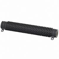
RES 5.0 OHM 10%300W EDGEWOUND WW
Manufacturer
Vishay
Series
HLZr
Datasheet
1.HLZ30007Z5R000KJ.pdf
(3 pages)
Specifications of HLZ30007Z5R000KJ
Resistance (ohms)
5
Power (watts)
300W
Composition
Wirewound
Temperature Coefficient
±50ppm/°C
Tolerance
±10%
Coating, Housing Type
Silicon Coated
Mounting Feature
Brackets (not included)
Size / Dimension
1.125" Dia x 8.500" L (28.58mm x 215.90mm)
Lead Style
Solder Lugs
Package / Case
Radial, Tubular
Lead Free Status / RoHS Status
Contains lead / RoHS non-compliant
Other names
HLZA-5.0


HLZ
Vishay Dale
DIMENSIONS in inches [millimeters]
Note
(1)
TERMINAL DIMENSIONS
MATERIAL SPECIFICATIONS
Element: Copper-nickel alloy of nickel-chrome alloy,
depending on resistance range
Core: Ceramic, steatite
Coating: Special high temperature silicone
Standard Terminals: Model “E” terminals are tinned steel
Terminal Bands: Steel
Part Marking: Vishay Dale, model, wattage, value,
tolerance, date code
MOUNTING HARDWARE
Mounting Hardware is available for HLZ resistors, see HL Brackets and Sliders datasheet for more information:
www.vishay.com/doc?30279
www.vishay.com
2
MODEL
HLZ033
HLZ090
HLZ099
HLZ105
HLZ110
HLZ140
HLZ165
HLZ220
HLZ240
HLZ275
HLZ300
HLZ375
Brackets are available for mounting HLZ series resistors - see “Mounting Hardware” section.
Style 06
and 07
A
C
10.500 [266.7]
4.000 [101.6]
4.000 [101.6]
4.500 [114.3]
4.000 [101.6]
6.500 [165.1]
6.000 [152.4]
6.500 [165.1]
8.000 [203.2]
8.500 [215.9]
2.000 [50.8]
3.500 [88.9]
LENGTH
[± 1.59]
± 0.062
B
CORE DIMENSIONS
D
0.563 [14.29]
0.563 [14.29]
0.750 [19.05]
0.750 [19.05]
0.750 [19.05]
1.125 [28.58]
0.750 [19.05]
1.125 [28.58]
1.125 [28.58]
1.125 [28.58]
1.125 [28.58]
1.125 [28.58]
Wirewound Resistors, Industrial Power, Edgewound
O.D.
Style 15
For technical questions, contact:
C
A
0.500 [12.70]
0.500 [12.70]
0.500 [12.70]
0.750 [19.05]
0.750 [19.05]
0.750 [19.05]
0.750 [19.05]
0.750 [19.05]
0.750 [19.05]
0.750 [19.05]
0.313 [7.94]
0.313 [7.94]
[± 0.79]
± 0.031
I.D.
B
D
TERMINAL
0.094 [2.38]
0.094 [2.38]
0.125 [3.18]
0.125 [3.18]
0.125 [3.18]
0.219 [5.56]
0.125 [3.18]
0.219 [5.56]
0.219 [5.56]
0.219 [5.56]
0.219 [5.56]
0.219 [5.56]
SETBACK
± 0.031
[± 0.79]
ww2bresistors@vishay.com
TERMINAL FINISH
“E” finish - 100 % Sn coated steel. “Z” finish - 60/40 Sn/Pb
coated steel. “N” finish - nickel coated steel. Finish for
terminal style 14 and 15 are limited to nickel plated steel (N).
DIMENSION
A
B
C
D
TERMINALS
DISTANCE
BETWEEN
(REF.)
1.437
3.312
2.812
4.812
5.312
6.812
7.312
9.312
2.75
3.25
3.75
5.75
Derating
120
100
80
60
40
20
0
- 65
0.563 [14.29]
0.250 [6.35]
0.166 [4.22]
0.020 [0.51]
STANDARD
TERMINAL DESIGNATION
0
25
06
06Z
06Z
06Z
06Z
06Z
07Z
06Z
07Z
07Z
07Z
07Z
07Z
50
AMBIENT TEMPERATURE IN °C
TERMINAL STYLE
0.625 [15.88]
150
0.375 [9.53]
0.173 [4.39]
0.020 [0.51]
OPTIONAL
Document Number: 30245
15N
15N
15N
15N
15N
15N
15N
15N
15N
15N
15N
15N
07
250
Revision: 17-Feb-11
101, 203, 301
101, 203, 301
102, 206, 303
102, 206, 303
102, 206, 303
103, 205, 303
102, 206, 303
103, 205, 303
103, 205, 303
103, 205, 303
103, 205, 303
103, 205, 303
0.594 [15.08]
0.250 [6.35]
0.065 [1.65]
0.031 [0.79]
BRACKET
TYPE
350
15
(1)
Related parts for HLZ30007Z5R000KJ
Image
Part Number
Description
Manufacturer
Datasheet
Request
R

Part Number:
Description:
357-036-542-201 CARDEDGE 36POS DL .156 BLK LOPRO
Manufacturer:
Vishay
Datasheet:
Part Number:
Description:
357-036-542-201 CARDEDGE 36POS DL .156 BLK LOPRO
Manufacturer:
Vishay
Datasheet:
Part Number:
Description:
357-036-542-201 CARDEDGE 36POS DL .156 BLK LOPRO
Manufacturer:
Vishay
Datasheet:
Part Number:
Description:
357-036-542-201 CARDEDGE 36POS DL .156 BLK LOPRO
Manufacturer:
Vishay
Datasheet:
Part Number:
Description:
357-036-542-201 CARDEDGE 36POS DL .156 BLK LOPRO
Manufacturer:
Vishay
Datasheet:
Part Number:
Description:
357-036-542-201 CARDEDGE 36POS DL .156 BLK LOPRO
Manufacturer:
Vishay
Datasheet:
Part Number:
Description:
357-036-542-201 CARDEDGE 36POS DL .156 BLK LOPRO
Manufacturer:
Vishay
Datasheet:
Part Number:
Description:
357-036-542-201 CARDEDGE 36POS DL .156 BLK LOPRO
Manufacturer:
Vishay
Datasheet:
Part Number:
Description:
357-036-542-201 CARDEDGE 36POS DL .156 BLK LOPRO
Manufacturer:
Vishay
Datasheet:
Part Number:
Description:
357-036-542-201 CARDEDGE 36POS DL .156 BLK LOPRO
Manufacturer:
Vishay
Datasheet:
Part Number:
Description:
357-036-542-201 CARDEDGE 36POS DL .156 BLK LOPRO
Manufacturer:
Vishay
Datasheet:
Part Number:
Description:
357-036-542-201 CARDEDGE 36POS DL .156 BLK LOPRO
Manufacturer:
Vishay
Datasheet:
Part Number:
Description:
357-036-542-201 CARDEDGE 36POS DL .156 BLK LOPRO
Manufacturer:
Vishay
Datasheet:
Part Number:
Description:
357-036-542-201 CARDEDGE 36POS DL .156 BLK LOPRO
Manufacturer:
Vishay
Datasheet:
Part Number:
Description:
357-036-542-201 CARDEDGE 36POS DL .156 BLK LOPRO
Manufacturer:
Vishay
Datasheet: