CNS-35-72 Tyco Electronics, CNS-35-72 Datasheet - Page 2
CNS-35-72
Manufacturer Part Number
CNS-35-72
Description
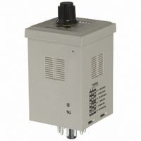
RELAY TIME DELAY 10A 120VAC-IN
Manufacturer
Tyco Electronics
Series
CNSr
Type
Multifunction - 4 Functionsr
Datasheet
1.CNS-35-92.pdf
(2 pages)
Specifications of CNS-35-72
Relay Type
Integrated
Function
Programmable (Multi-Function)
Circuit
DPDT (2 Form C)
Delay Time
0.1 Sec ~ 100 Min
Output Type
Mechanical Relay
Contact Rating @ Voltage
10A @ 277VAC
Voltage - Supply
120VAC
Mounting Type
Socket
Termination Style
8 Pin Socketable
Timing Adjustment Method
Hand Dial
Timing Initiate Method
Input Voltage
Time Range
0.1 Sec. To 100 Min.
No. Of Pins
8
Time Range Min
0.1s
Peak Reflow Compatible (260 C)
No
Signal Input Type
Fixed Voltage
Supply Voltage
120VAC
Display Type
Time Delay Relay
Timing Range
0.1 s to 100 min
Contact Form
DPDT
Contact Rating
10 A
Mode Of Operation
Programmable - 4 Timing Functions
Lead Free Status / RoHS Status
Lead free / RoHS Compliant
Lead Free Status / RoHS Status
Contains lead / RoHS non-compliant, Lead free / RoHS Compliant
Other names
1393124-2
PB556
PB556


1214
Mounting Clip Dimensions
SSA-24C667
Mouting Clip
DIP Switch Layout
Interval On (Input Controlled)
initiated at the same time with the relay de-energizing at the completion of the time interval.
state of the relay.
Recycler (Initially On)
power. The initial state of the relay will be energized.
inhibit timing until it is once again opened, at which time it will start from zero time.
2.283
(58.0)
Delay on Operate
by the application of input voltage.
energize the relay and reset the timer. Opening the switch will initiate another time interval.
Closing the control switch during timing will reset the time to zero and inhibit timing until
opened again.
Recycler (Initially Off)
power. The initial state of the relay will be de-energized.
and inhibit timing until it is once again opened, at which time it will start from zero time.
Note: The solid black blocks in the DIP switch diagrams indicate the switch positions. For
Timing Function Descriptions and Switch Settings
Dimensions are shown for
reference purposes only.
8 Or 11 Pin
1
1
72 & 92 - Output relay will begin cycling at a 50% duty cycle with the application of input
76 & 96 - Same as the above except, closing the control switch will energize the relay and
1
1
72 & 92 - Output relay will begin cycling at a 50% duty cycle with the application of input
76 & 96 - Same as the above except, closing the control switch will de-energize the relay
72 & 92 - Output relay is energized by the application of input voltage. The time interval is
76 & 96 - Same as above. Closing the control switch will have no effect on timing or the
72 & 92 - Output relay is energized at the completion of the time interval which is initiated
76 & 96 - Same as the above except, closing the control switch after time out will de-
2.047
(52.0)
example, all the switches are “off” in the diagram above.
(50.0)
1.970
2
2
2
2
On
3
3
3
3
1
(42.0)
(48.0)
1.654
1.890
4
4
4
4
Function
2
Setting
3
(15.0)
.591
4
Dimensions are in inches over
(millimeters) unless otherwise
specified.
5
Setting
Time
6
7
Catalog 1308242
Issued 3-03
Timing Range Switch Settings
11 Pin Only
Interval On (Switch Controlled)
closed or the closing of the control switch with the input applied. Immediately upon either,
timing is initiated with the relay de-energizing at the completion of the time interval. Closing the
control switch after time out will reset the timer, energize the relay, and initiate another time
interval. Closing the control switch during timing will have no effect on timing or the state of the
relay.
Delay on Release
or the application of input voltage with the control switch already closed. The time interval will
be initiated by the opening of the control switch with the relay de-energizing at the completion
of the time interval. Closing the control switch after time out will energize the relay in
preparation for another time interval. Closing the control switch during timing will reset the
time to zero and inhibit timing until opened again.
Inverted Delay on Release
control switch is open. Control switch closing will de-energize the relay. A timing interval will
be initiated with the opening of the control switch, at the completion of which the relay
willenergize. With the control switch closed upon application of input voltage, the relay will
wait until the control switch is opened to initiate a time interval after which the relay will
energize. Closing of the control switch during timing will reset the time to zero and inhibit
timing until opened again.
Interval Off
the control switch is open. Control switch closing will de-energize the relay and start a time
interval. At the completion of the time interval, the relay will energize. With the control switch
closed upon application of input voltage, a time interval will be initiated after which the relay will
energize. Closing of the control switch during timing will have no effect on timing or the state
of the relay.
76 & 96 - Output relay is energized by the closing of the control switch with the input applied
1
1
1
76 & 96 - Output relay will initially be energized with the application of the input voltage when
5
5
5
1
76 & 96 - Output relay is energized by the application of input voltage with the control switch
72 & 92 - No Time Delay - Instantly On
76 & 96 - Output relay will energize with the application of the input voltage when the
DIP Switch
Setting
2
6
6
6
2
2
2
Specifications and availability
subject to change.
7
7
7
3
3
3
3
0.1 - 1.0 Second
1.0 - 10 Seconds
10 - 100 Seconds
4
Timing Range
4
4
4
5
5
5
DIP Switch
Setting
6
6
6
7
7
7
www.tycoelectronics.com
Technical support:
Refer to inside back cover.
0.1 - 1.0 Minute
1.0 - 10 Minutes
10 - 100 Minutes
Timing Range
P&B
Related parts for CNS-35-72
Image
Part Number
Description
Manufacturer
Datasheet
Request
R

Part Number:
Description:
RELAY TIME-DELAY 10A 24-240V
Manufacturer:
Tyco Electronics
Datasheet:
Part Number:
Description:
RELAY TIME DELAY 10A 120VAC-IN
Manufacturer:
Tyco Electronics
Datasheet:
Part Number:
Description:
RELAY TIME-DELAY 10A 24-240VAC
Manufacturer:
Tyco Electronics
Datasheet:
Part Number:
Description:
RELAY TIME DELAY 240V
Manufacturer:
TE Connectivity
Datasheet:

Part Number:
Description:
Battery Interconnection System for Portable Electronics; BU CONN FS6 8POS DIP TYPE ASSY ( AMP )
Manufacturer:
Tyco Electronics
Part Number:
Description:
Manufacturer:
Tyco Electronics
Datasheet:
Part Number:
Description:
Manufacturer:
Tyco Electronics
Datasheet: