88865155 Crouzet USA, 88865155 Datasheet - Page 6
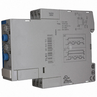
88865155
Manufacturer Part Number
88865155
Description
RELAY TIME ANALG 10A 24-240V DIN
Manufacturer
Crouzet USA
Series
TLR1r
Specifications of 88865155
Time Range
1sec To 100hr
Power Consumption
1.5W
Reset Time
100ms
Supply Voltage Ac, Max
240V
Mounting Type
DIN Rail
Time Range Min
0.1s
Supply Voltage Min
24V
Relay Type
Integrated
Function
Repeat Cycle
Circuit
SPDT (1 Form C)
Delay Time
0.1 Sec ~ 100 Hrs
Output Type
Mechanical Relay
Contact Rating @ Voltage
10A @ 250VAC
Voltage - Supply
24 ~ 240VAC
Termination Style
Screw Terminal
Timing Adjustment Method
Hand Dial
Timing Initiate Method
Input Voltage
Contact Form
SPDT
Current, Rating
10 A
Power, Rating
2000⁄80 VA⁄W
Repeatability
±0.5 %
Standards
UL, cUL, CSA, CE
Temperature, Operating, Maximum
60 °C
Temperature, Operating, Minimum
-20 °C
Termination
Screw
Timer Type
Repeat Cycle
Timing Range
0.1 to 1 sec., 1 to 10 sec., 6 to 60 sec., 1 to 10 min., 6 to 60 min., 1 to 10 hrs., 10 to 100 hrs.
Voltage, Control
240⁄24 VAC⁄VDC
Voltage, Rating
250 V
Supply Voltage
24 V to 240 V
Contact Rating
8 A at 250 VAC
Signal Input Type
Volt-Free Contact
Supply Current
10A
Rohs Compliant
Yes
Lead Free Status / RoHS Status
Lead free / RoHS Compliant
Lead Free Status / RoHS Status
Lead free / RoHS Compliant, Lead free / RoHS Compliant
Other names
646-1181


Function Ht :
Provides a cumulative time for contact opening.
On energisation, the output changes state,
remains in that state for the duration of timing
and resets at the end of the single cycle.
Function K:
On energisation, the output changes state.
On de-energisation timing commences and
the output only returns to the reset condition
after timing.
Function L :
Repetitive cycle comprising 2 independent
adjustable time bases. Each time base
corresponds alternately to a different output
state.
N.B. : The cycle starts with the output in the
rest position.
Function Li :
Repetitive cycle comprising 2 independent
adjustable time bases. Each time base
corresponds alternately to a different output
state.
N.B. : The cycle starts with the output in the
operating position.
Function N :
At the first control pulse the output is
energised.
To complete the timing the interval between
the two control pulses must be greater than
the timing set.
Function O :
On energisation, a first timing sequence
occurs and the output changes state.
With the closing of the control contact, the
output resets and the timing starts, with the
output being activated after timing.
For the timing to be completed, the interval
between the closing of two control contacts
must be greater than the timing set.
Delay on de-energisation - True delay OFF
2 relays timed or
1 relay timed and 1 instantaneous
Delay on energisation
2 relays timed or
1 relay timed and 1 instantaneous
with memory
Repeat cylce - Cyclic timing - Asymmetrical recycler
Repeat cylce - Cyclic timing - Asymmetrical recycler
2 relays timed or
1 relay timed and 1 instantaneous
2 relays timed or
1 relay timed and 1 instantaneous
"Safe-guard"
"Delayed safe-guard".
R1/R2
R1/R2
R2 Inst.
R1/R2
U
R
U
C
R
1 relay
U
R
U
1 relay
U
C
R
U
R1
R2
U
1 relay
U
C
R
1 relay
U
R
U
C
T1
T1
T1
T1
T
T2
T2
T2
T2
T
t1
t1
T = t1+t2
T = t1+t2
T
T
T
T
t2
t2
4/ii
Function Pt :
Calculates the total opening time of a contact.
At the end of timing, the output is energised
for approximately 500 ms.
Function T :
After power-up, pressing or holding down the
switch closes the relay. Pressing the switch a
second time opens the relay.
Function Tt :
After power-up, pressing or holding down the
switch closes the relay and starts timing. The
relay opens at the end of timing or when the
switch is pressed a second time.
Function P :
Timing begins on energisation. At the end of
the timing period output relay R (or the load)
changes state for a period of approx. 500
milliseconds.
Function Q :
At the end of timing, the output is not
energised. It remains "open" (not
conducting) and will only change state
after the fixed time of Ti has elapsed.
Dwell time selectable
Function T :
energisation with memory
a - energisation by control signal
The timer sums the times for which the
control contact is closed (C1).
Reset is by the reset signal (C2) only.
b - energisation by supply voltage
The timer sums the times for which the
supply voltage (U) is on.
Reset is by the reset signal (C2) only
Function W :
After energisation, if the control contact
opens it causes output relay R (or the load)
to change state and timing to start. At the
end of the timing period, relay R resets to its
original state.
Timing on
Impulse relay
Impulse counter (delay on)
Timed impulse relay
Delayed fixed-length pulse
Star-delta"
Timing after pulse on control contact
U
R
U
R
U
C
R
U
C
R
U
C
R
U
C
R
t1
T= t1+t2
T
T
P = 500 ms
T
P
t2
T
Ti
P
t
4
Related parts for 88865155
Image
Part Number
Description
Manufacturer
Datasheet
Request
R

Part Number:
Description:
SCREW SOCKET (OT08PC)
Manufacturer:
Crouzet USA
Datasheet:

Part Number:
Description:
PANEL PLATE FOR 813
Manufacturer:
Crouzet USA
Datasheet:
Part Number:
Description:
Controller; CTD46 Dual Display Temperature, 1/16 DIN, NEMA 4X, 110/220VAC
Manufacturer:
Crouzet USA
Datasheet:

Part Number:
Description:
11R1084
Manufacturer:
Crouzet USA
Datasheet:
Part Number:
Description:
11R1086
Manufacturer:
Crouzet USA
Datasheet:
Part Number:
Description:
11R1087
Manufacturer:
Crouzet USA
Datasheet:
Part Number:
Description:
11R1089
Manufacturer:
Crouzet USA
Datasheet:
Part Number:
Description:
11R1078
Manufacturer:
Crouzet USA
Datasheet:
Part Number:
Description:
11R1079
Manufacturer:
Crouzet USA
Datasheet: