LT4H-DC24VS Panasonic Electric Works, LT4H-DC24VS Datasheet - Page 17
LT4H-DC24VS
Manufacturer Part Number
LT4H-DC24VS
Description
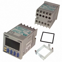
TIMER RELAY DIG 24VDC SCREW TERM
Manufacturer
Panasonic Electric Works
Series
LT4Hr
Datasheet
1.LT4H-DC24VS.pdf
(39 pages)
Specifications of LT4H-DC24VS
Lead Free Status / RoHS Status
Lead free / RoHS Compliant
Other names
255-1217


6) Long periods of continuous operation
in the time-up completed condition (one
month or more) will result in the weaken-
ing of the internal electrical components
from the generated heat and, therefore,
should be avoided. If you do plan to use
the unit for such continuous operation,
use in conjunction with a relay as shown
in the circuit in the diagram below.
7. Self-diagnosis function
If a malfunction occurs, one of the following displays will appear.
Note: Includes the possibility that the EEPROM’s life has expired.
R
Display
R
Relay
T
T
Malfunctioning CPU.
Malfunctioning memory. See
note.
Timer
R
Receive output
from contact
at relay R
Contents
R
7. Acquisition of CE marking
Please abide by the conditions below
when using in applications that comply
with EN61812-1.
1) Overvoltage category III,
pollution level 2
2) This timer employs a power supply
without a transformer, so the power and
input signal terminals are not insulated.
(1) When a sensor is connected to the
input circuit, install double insulation on
the sensor side.
(2) In the case of contact input, use dual-
insulated relays, etc.
3) The load connected to the output con-
tact should have basic insulation.
This timer is protected with basic insula-
tion and can be double-insulated to meet
EN/IEC requirements by using basic
insulation on the load.
PRECAUTIONS IN USING THE LT4H SERIES
Output condition
OFF
Enter reset input, RESET
key, or restart unit.
Restoration procedure
4) Please use a power supply that is pro-
tected by an overcurrent protection
device which complies with the EN/IEC
standard (example: 250 V 1 A fuse, etc.).
5) You must use a terminal socket or
socket for the installation. Do not touch
the terminals or other parts of the timer
when it is powered. When installing or
un-installing, make sure that no voltage
is being applied to any of the terminals.
6) Do not use this timer as a safety cir-
cuit. For example when using a timer in a
heater circuit, etc., provide a protection
circuit on the machine side.
The values at start-up before the CPU
malfunction occurred.
Preset values after restoration
0
49
Related parts for LT4H-DC24VS
Image
Part Number
Description
Manufacturer
Datasheet
Request
R

Part Number:
Description:
TIMER RELAY DIGITAL 240VAC SCREW
Manufacturer:
Panasonic Electric Works
Datasheet:

Part Number:
Description:
TIMER RELAY DIGITAL 240VAC 11PIN
Manufacturer:
Panasonic Electric Works
Datasheet:
Part Number:
Description:
TIMER RELAY DIG 24VDC OCT 11PIN
Manufacturer:
Panasonic Electric Works
Datasheet:

Part Number:
Description:
Timer Multifunction
Manufacturer:
NAIS
Datasheet:

Part Number:
Description:
TIMER DIGITAL 24VDC SCREW TERM
Manufacturer:
Panasonic Electric Works
Datasheet:
Part Number:
Description:
Manufacturer:
Panasonic Electric Works
Datasheet:
Part Number:
Description:
Manufacturer:
Panasonic Electric Works
Datasheet:

Part Number:
Description:
CONN SOCKET P4 .4MM 50POS SMD
Manufacturer:
Panasonic Electric Works
Datasheet:
Part Number:
Description:
CONN SOCKET .8MM 16POS SMD
Manufacturer:
Panasonic Electric Works
Datasheet:
Part Number:
Description:
CONN HEADER .8MM 16POS SMD
Manufacturer:
Panasonic Electric Works
Datasheet:
Part Number:
Description:
CONN SOCKET .8MM 20POS SMD
Manufacturer:
Panasonic Electric Works
Datasheet:
Part Number:
Description:
CONN SOCKET .8MM 20POS SMD
Manufacturer:
Panasonic Electric Works
Datasheet:
Part Number:
Description:
CONN HEADER .8MM 20POS SMD
Manufacturer:
Panasonic Electric Works
Datasheet:
Part Number:
Description:
CONN SOCKET .8MM 22POS SMD
Manufacturer:
Panasonic Electric Works
Datasheet:
Part Number:
Description:
CONN SOCKET .8MM 30POS SMD
Manufacturer:
Panasonic Electric Works
Datasheet: