CPC1945G Clare, CPC1945G Datasheet - Page 2
CPC1945G
Manufacturer Part Number
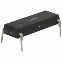
CPC1945G
Description
RELAY SSR 1A 16-DIP
Manufacturer
Clare
Series
CPCr
Specifications of CPC1945G
Circuit
SPST-NO (1 Form A)
Output Type
AC, Zero Cross
Load Current
1A
Voltage - Input
1.2VDC
Voltage - Load
0 ~ 400 V
Mounting Type
Through Hole
Termination Style
PC Pin
Package / Case
16-DIP (0.300", 7.62mm), 4 Leads
Input Type
DC
Input Voltage (max)
1.4V
Isolation Voltage
3750(RMS)V
Package Type
PDIP
Output Device
SCR
Pin Count
4
Mounting
Through Hole
Operating Temp Range
-40C to 85C
Operating Temperature Classification
Industrial
Rad Hardened
No
Lead Free Status / RoHS Status
Lead free / RoHS Compliant
On-state Resistance
-
Lead Free Status / Rohs Status
Compliant
Other names
CLA162


Absolute Maximum Ratings @ 25ºC
1 Derate linearly 1.33 mW / ºC
2 Derate linearly 16.6 mW / ºC
Electrical Characteristics @ 25ºC
1
2
3
4
2
Parameter
Blocking Voltage
Reverse Input Voltage
Input Control Current
Input Power Dissipation
P
Isolation Voltage, Input to Output
Operational Temperature
Storage Temperature
Parameters
Output Characteristics
Operating Voltage Range
Load Current, Continuous
Non-Repetitive Single Cycle Surge Current
Off State Leakage Current
On-State Voltage Drop
Critical Rate of Rise
Switching Speeds
Zero-Cross Turn-On Voltage
Operating Frequency
Load Power Factor for Guaranteed Turn-On
Input Characteristics
Input Control Current
Input Voltage Drop
Input Drop-out Voltage
Reverse Input Current
Common Characteristics
Input to Output Capacitance
Zero Cross 1st half-cycle @ <100Hz
Snubber circuits may be required at low power factors.
Tested in accordance with EIA/NARM standard RS-443.
For high noise environments, use I
MAX
Peak (10ms)
Turn-on
Turn-off
, Total Package Dissipation
3
1
4
1
F
=10mA.
2
2
-40 to +125
Subsequent half-cycle
Ratings
-40 to +85
1600
3750
400
100
150
Conditions
1st half-cycle
5
1
V
V
L
I
I
I
=120V
L
L
F
V
F
=400V
=1A
=5 mA
=5mA
R
V
=5V
-
-
-
-
-
-
-
L
rms
Units
rms
V
P
www.clare.com
mW
mW
mA
°C
°C
V
V
A
rms
P
Symbol
dV/dt
I
I
C
LEAK
PF
TSM
t
V
t
I
I
I
on
-
-
-
-
-
off
F
R
I/O
Absolute Maximum Ratings are stress ratings. Stresses in
excess of these ratings can cause permanent damage to
the device. Functional operation of the device at conditions
beyond those indicated in the operational sections of this
data sheet is not implied.
L
F
0.005
Min
1000
0.25
0.9
0.8
20
20
-
-
-
-
-
-
-
-
-
-
Typ
0.8
1.2
2
1
3
-
-
-
-
-
-
-
-
-
-
-
-
Max
120
400
1.6
0.5
0.5
1.4
10
10
10
1
1
5
-
-
-
-
-
Units
cycles
V/µs
V
A
V
mA
mA
Hz
µA
pF
A
V
V
V
V
rms
rms
rms
-
CPC1945G
R05
Related parts for CPC1945G
Image
Part Number
Description
Manufacturer
Datasheet
Request
R

Part Number:
Description:
RELAY OPTOMOS SP-NO 100MA 4-SOP
Manufacturer:
Clare
Datasheet:
Part Number:
Description:
RELAY OPTOMOS SP-NO 300MA 4-SOP
Manufacturer:
Clare
Datasheet:
Part Number:
Description:
RELAY OPTOMOS SP-NO 120MA 4-SOP
Manufacturer:
Clare
Datasheet:
Part Number:
Description:
RELAY OPTOMOS SP-NO 100MA 4-SOP
Manufacturer:
Clare
Datasheet:
Part Number:
Description:
RELAY OPTOMOS 700MA 4-SOP
Manufacturer:
Clare
Datasheet:
Part Number:
Description:
RELAY OPTOMOS SP-NO 150MA 4-SOP
Manufacturer:
Clare
Datasheet:
Part Number:
Description:
RELAY OPTOMOS SP-NO 100MA 4-SOP
Manufacturer:
Clare
Datasheet:
Part Number:
Description:
RELAY OPTOMOS SP-NO 100MA 4-SOP
Manufacturer:
Clare
Datasheet:
Part Number:
Description:
RELAY OPTOMOS SP-NO 300MA 4-SOP
Manufacturer:
Clare
Datasheet:
Part Number:
Description:
RELAY OPTOMOS SP-NO 120MA 4-SOP
Manufacturer:
Clare
Datasheet:

Part Number:
Description:
4 Pin SOP OptoMOS Relay
Manufacturer:
CLARE [Clare, Inc.]
Datasheet:


Part Number:
Description:
MOSFET N-CH 350V 5MA SOT-223
Manufacturer:
Clare
Datasheet: