ARJ2003 Panasonic Electric Works, ARJ2003 Datasheet - Page 5
ARJ2003
Manufacturer Part Number
ARJ2003
Description
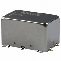
RELAY 3VDC 8GHZ 200MW PCB
Manufacturer
Panasonic Electric Works
Series
ARJr
Datasheet
1.ARJ22A12.pdf
(5 pages)
Specifications of ARJ2003
Relay Type
RF
Circuit
DPDT (2 Form C)
Contact Rating @ Voltage
0.3A @ 30VDC
Coil Type
Standard
Coil Current
66.7mA
Coil Voltage
3VDC
Control On Voltage (max)
2.25 VDC
Control Off Voltage (min)
0.3 VDC
Mounting Type
Through Hole
Termination Style
PC Pin
Lead Free Status / RoHS Status
Lead free / RoHS Compliant
Available stocks
Company
Part Number
Manufacturer
Quantity
Price
Company:

Part Number:
ARJ2003
Manufacturer:
PANASONIC
Quantity:
12 000


8. Measuring method (Impedance 50Ω)
Connector
(Step 1) Calibrate the test system with
(Step 2) After calibration, connect the
Notes:
1. All bottom surface of the base should be touched
closely or soldered with PC board ground.
2. 4 ribs should be soldered with PC board ground.
Measuring board
1) Dimensions
<Surface mount terminal>
H P
No.
Network
analyzer
1
2
20.00
.787
7.07
.278
8 5 1 0 C
RF
OUT
2.81
.111
1.00
.039
HP 85131-60013
B
A
R
Product name
HP calibration kit [HP85052B]
D.U.T. board and measure.
Connect 50 Ω terminals on
connectors other than those for
measurement.
HP 83059
0.80
.031
0.40
.016
H P
B
A
R
RF
IN
6-1.76
6-.069
S parameter
test set
8 5 1 5 A
17.00
12.04
30.00
1.181
.669
8.89
.350
.474
8.35
.329
PORT2
PORT1
0.40
.016
3.5 mm testport,
Extension cable
3.5 mm coaxial
0.40
.016
0.40
.016
Contents
adaptor
All Rights Reserved © COPYRIGHT Panasonic Electric Works Co., Ltd.
1
1
7.22
.284
2
2
<Standard PC board terminal>
<Calibration board>
2) Material: Glass PTFE double-sided
through hole PC board R-4737
(Panasonic Electric Works)
3) Board thickness: t = 0.8 mm
4) Copper plating: 18µm
• Connector (SMA type receptacle)
Product name: R125 510 (RADIALL)
Insertion loss compensation
The insertion loss of relay itself is given
by subtracting the insertion loss of short-
circuit the Com and the NC (or NO).
(signal path and two connectors)
9. Others
1) The switching lifetime is defined under
the standard test condition specified in
the JIS* C 5442-1996 standard
(temperature 15 to 35°C
humidity 25 to 75%). Check this with the
real device as it is affected by coil driving
circuit, load type, activation frequency,
activation phase, ambient conditions and
other factors.
Also, be especially careful of loads such
as those listed below.
20.00
.787
7.62
.300
3.81
.150
6.62
.261
10.0
.394
0.90
.035
0.50
.020
6-1.86
6-.073
14.5
.571
12.70
17.00
11.70
30.00
1.181
8.35
.329
.500
.669
8.89
.350
.461
0.40 or 0.50
.016 or .020
1.76 or 1.86
.069 or .073
59 to
0.50
.020
0.40
.016
0.40
.016
95°F,
1.00
.039
6.72
.265
• When used for AC load-operating and
the operating phase is synchronous.
Rocking and fusing can easily occur due
to contact shifting.
• High-frequency load-operating
When high-frequency opening and
closing of the relay is performed with a
load that causes arcs at the contacts,
nitrogen and oxygen in the air is fused by
the arc energy and HNO
can corrode metal materials.
Three countermeasures for these are
listed here.
(1) Incorporate an arc-extinguishing
circuit.
(2) Lower the operating frequency
(3) Lower the ambient humidity
2) Use the relay within specifications
such as coil rating, contact rating and on/
off service life. If used beyond limits, the
relay may overheat, generate smoke or
catch fire.
3) Be careful not to drop the relay. If
accidentally dropped, carefully check its
appearance and characteristics before
use.
4) Be careful to wire the relay correctly.
Otherwise, malfunction, overheat, fire or
other trouble may occur.
5) If a relay stays on in a circuit for many
months or years at a time without being
activated, circuit design should be
reviewed so that the relay can remain
non-excited. A coil that receives current
all the time heats, which degrades
insulation earlier than expected. A
latching type relay is recommended for
such circuits.
6) The latching type relay is shipped in
the reset position. But jolts during
transport or impacts during installation
can change the reset position. It is,
therefore, advisable to build a circuit in
which the relay can be initialized (set and
reset) just after turning on the power.
7) If silicone materials (e.g., silicone
rubbers, silicone oils, silicone coating
agents, silicone sealers) are used in the
vicinity of the relay, the gas emitted from
the silicone may adhere to the contacts of
the relay during opening and closing and
lead to improper contact. If this is the
case, use a material other than silicone.
8) We recommend latching type when
using in applications which involve
lengthy duty cycles.
* Japanese Industrial Standards
For general cautions for use, please
refer to the “General Application
Guidelines”.
3
RJ (ARJ)
is formed. This
Related parts for ARJ2003
Image
Part Number
Description
Manufacturer
Datasheet
Request
R

Part Number:
Description:
Manufacturer:
Panasonic Electric Works
Datasheet:
Part Number:
Description:
Manufacturer:
Panasonic Electric Works
Datasheet:

Part Number:
Description:
CONN SOCKET P4 .4MM 50POS SMD
Manufacturer:
Panasonic Electric Works
Datasheet:
Part Number:
Description:
CONN SOCKET .8MM 16POS SMD
Manufacturer:
Panasonic Electric Works
Datasheet:
Part Number:
Description:
CONN HEADER .8MM 16POS SMD
Manufacturer:
Panasonic Electric Works
Datasheet:
Part Number:
Description:
CONN SOCKET .8MM 20POS SMD
Manufacturer:
Panasonic Electric Works
Datasheet:
Part Number:
Description:
CONN SOCKET .8MM 20POS SMD
Manufacturer:
Panasonic Electric Works
Datasheet:
Part Number:
Description:
CONN HEADER .8MM 20POS SMD
Manufacturer:
Panasonic Electric Works
Datasheet:
Part Number:
Description:
CONN SOCKET .8MM 22POS SMD
Manufacturer:
Panasonic Electric Works
Datasheet:
Part Number:
Description:
CONN SOCKET .8MM 30POS SMD
Manufacturer:
Panasonic Electric Works
Datasheet:
Part Number:
Description:
CONN HEADER .8MM 30POS SMD
Manufacturer:
Panasonic Electric Works
Datasheet:
Part Number:
Description:
CONN SOCKET .8MM 30POS SMD
Manufacturer:
Panasonic Electric Works
Datasheet:
Part Number:
Description:
CONN SOCKET .8MM 30POS SMD
Manufacturer:
Panasonic Electric Works
Datasheet:
Part Number:
Description:
CONN HEADER .8MM 30POS SMD
Manufacturer:
Panasonic Electric Works
Datasheet:
Part Number:
Description:
CONN HEADER BRD/BRD .5MM 60POS
Manufacturer:
Panasonic Electric Works
Datasheet: