RP1-24V Panasonic Electric Works, RP1-24V Datasheet - Page 2
RP1-24V
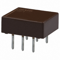
Manufacturer Part Number
RP1-24V
Description
RELAY HIGH FREQ 24VDC PC MNT
Manufacturer
Panasonic Electric Works
Series
RPr
Datasheet
1.RP1-5V.pdf
(5 pages)
Specifications of RP1-24V
Relay Type
RF
Circuit
SPDT (1 Form C)
Contact Rating @ Voltage
0.1A @ 30VDC
Coil Type
Standard
Coil Current
11.3mA
Coil Voltage
24VDC
Control On Voltage (max)
18 VDC
Control Off Voltage (min)
2.4 VDC
Mounting Type
Through Hole
Termination Style
PC Pin
Lead Free Status / RoHS Status
Lead free / RoHS Compliant
Other names
255-1091
Available stocks
Company
Part Number
Manufacturer
Quantity
Price


2. Specifications
Note: * The upper operation ambient temperature limit is the maximum temperature that can satisfy the coil temperature rise value. Refer to [6] AMBIENT ENVIRONMENT
REFERENCE DATA
1. High frequency characteristics
Sample: RP1-6V
Measuring method: Impedance 50Ω
Measuring tool:
• V.S.W.R
Contact
Rating
High frequency
characteristics (Initial)
(Impedance 50Ω)
Electrical
characteristics
Mechanical
characteristics
Expected life
Conditions
Unit weight
Characteristics
in GENERAL APPLICATION GUIDELINES.
3.0
2.8
2.6
2.4
2.2
2.0
1.8
1.6
1.4
1.2
1.0
0
0.2
0.4
0.6
NO (Terminal Nos. 5-6)
Arrangement
Initial contact resistance, max.
Contact material
Contact rating
Nominal operating power (single side stable type)
V.S.W.R.
Insertion loss (without D.U.T. board’s loss)
Isolation
Insulation resistance (Initial)
Breakdown
voltage (Initial)
Temperature rise (at 20°C)
Operate time (at 20°C)
Release time (at 20°C)
Shock
resistance
Vibration
resistance
Mechanical
Electrical
Conditions for operation, transport and storage*
Max. operating speed (at rated load)
0.8
Frequency, GHz
NC (Terminal Nos. 4-5)
1.0
1.2
1.4
18.00
.709
1.6
6–1.00 dia
.039 dia
Between open contacts
Between contact and coil
Functional
Destructive
Functional
Destructive
All Rights Reserved © COPYRIGHT Panasonic Electric Works Co., Ltd.
1.8
7.62
.300
0.60
.024
2.0
6–1.60 dia
.063 dia
Item
18.92
.745
• Insertion loss
1.94
.076
SMA connector
5.08
.200
Soldering
6–2.30 dia
.090 dia
26–0.80 dia
.031 dia
4.22
.166
5
4
3
2
1
0
0
9.82
.387
0.2
0.4
mm
N.C. (Terminal Nos. 4-5)
0.6
1 Form C
Max.50mΩ (By voltage drop 6V DC 0.1A)
Stationary: Ag + Au clad, Movable: AgPd
0.1A 30V DC (resistive load); Contact carrying power: 3W (Max. 1.2GHz);
1W (Max. 1.8GHz); Contact switching power: 1W (Max. 1.8GHz)
140mW (1.5 to 12V DC), 270mW (24V DC)
Max. 1.2 (at 1GHz), Max. 1.3 (at 1.8GHz)
Max. 0.5dB (at 1GHz), Max. 1dB (at 1.8GHz)
Min. 15dB (at 1GHz), Min. 10dB (at 1.8GHz)
Min. 1,000MΩ (at 500V DC)
Measurement at same location as “Initial breakdown voltage” section.
750 Vrms for 1min. (Detection current: 10mA)
1,500 Vrms for 1min. (Detection current: 10mA)
Max. 50°C (By resistive method, nominal voltage applied to the coil, contact carrying
power: 1W/at 1.8GHz)
Max. 3ms (Approx. 1.5ms) (Nominal operating voltage applied to the coil, excluding
contact bounce time.)
Max. 2ms (Approx. 1ms) (Nominal operating voltage applied to the coil, excluding contact
bounce time.) (without diode)
Min. 500 m/s
Min. 1,000 m/s
10 to 55 Hz at double amplitude of 3mm (Detection time: 10µs.)
10 to 55 Hz at double amplitude of 5mm
Min. 5×10
Min. 10
Ambient temperature: –40°C to +70°C
Humidity: 5 to 85% R.H. (Not freezing and condensing at low temperature)
20 cpm (at rated load)
Approx. 1 g
inch
N.O. (Terminal Nos. 5-6)
0.8
Frequency, GHz
5
1.0
PC board
• Double-sided through hole
• Material: Glass-epoxy resin
• t = 1.0mm
• Copper plated thickness: 35 µm
(0.1A 30V DC resistive load, 1W (at 1.8GHz, V.S.W.R. max. 1.3 at 20 cpm)
6
1.2
(at 180 cpm)
.04 oz
2
{Approx. 50G} (Half-wave pulse of sine wave: 11ms; detection time: 10µs.)
1.4
2
{Approx. 100G} (Half-wave pulse of sine wave: 6ms.)
1.6
.039 inch
1.8
2.0
• Isolation
Specifications
–40°F to +158°F
100
90
80
70
60
50
40
30
20
10
0
0
0.2
0.4
0.6
0.8
Frequency, GHz
1.0
1.2
1.4
1.6
1.8
RP
2.0
Related parts for RP1-24V
Image
Part Number
Description
Manufacturer
Datasheet
Request
R

Part Number:
Description:
RELAY HIGH FREQ 5VDC PC MNT
Manufacturer:
Panasonic Electric Works
Datasheet:
Part Number:
Description:
RELAY HIGH FREQ 12VDC PC MNT
Manufacturer:
Panasonic Electric Works
Datasheet:
Part Number:
Description:
RELAY HI FREQ 1.5VDC PCB MOUNT
Manufacturer:
Panasonic Electric Works
Datasheet:
Part Number:
Description:
RELAY HI FREQ 3VDC PCB MOUNT
Manufacturer:
Panasonic Electric Works
Datasheet:
Part Number:
Description:
RELAY HI FREQ 4.5VDC PCB MOUNT
Manufacturer:
Panasonic Electric Works
Datasheet:
Part Number:
Description:
RELAY HI FREQ 6VDC PCB MOUNT
Manufacturer:
Panasonic Electric Works
Datasheet:
Part Number:
Description:
RELAY HI FREQ 9VDC PCB MOUNT
Manufacturer:
Panasonic Electric Works
Datasheet:
Part Number:
Description:
RELAY HI FREQ 12VDC SELF-CLINCH
Manufacturer:
Panasonic Electric Works
Datasheet:
Part Number:
Description:
RELAY HI FREQ 4.5VDC SELF-CLINCH
Manufacturer:
Panasonic Electric Works
Datasheet:
Part Number:
Description:
RELAY HI FREQ 5VDC SELF-CLINCH
Manufacturer:
Panasonic Electric Works
Datasheet:

Part Number:
Description:
Manufacturer:
Panasonic Electric Works
Datasheet:
Part Number:
Description:
Manufacturer:
Panasonic Electric Works
Datasheet:

Part Number:
Description:
CONN SOCKET P4 .4MM 50POS SMD
Manufacturer:
Panasonic Electric Works
Datasheet:
Part Number:
Description:
CONN SOCKET .8MM 16POS SMD
Manufacturer:
Panasonic Electric Works
Datasheet:
Part Number:
Description:
CONN HEADER .8MM 16POS SMD
Manufacturer:
Panasonic Electric Works
Datasheet: