TN2-L2-12V Panasonic Electric Works, TN2-L2-12V Datasheet
TN2-L2-12V
Manufacturer Part Number
TN2-L2-12V
Description
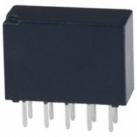
RELAY LATCHING 1A 12VDC PC MNT
Manufacturer
Panasonic Electric Works
Series
TNr
Type
General Purpose Relayr
Specifications of TN2-L2-12V
Relay Type
General Purpose
Circuit
DPDT (2 Form C)
Contact Rating @ Voltage
1A @ 30VDC
Coil Type
Latching, Dual Coil
Coil Current
16.7mA
Coil Voltage
12VDC
Control On Voltage (max)
9 VDC
Mounting Type
Through Hole
Termination Style
PC Pin
Brand/series
TN Series
Contact Form
DPDT
Current, Rating
0.5⁄1 AAC⁄ADC
Diameter, Mounting
0.039 in.
Dimensions
0.551 in. L x 0.220 in. W x 0.386 in. H
Function
General Purpose
Latch Type
2 Coil
Material, Contact
Gold-Clad Silver
Number Of Pins
10
Power, Rating
30 W
Standards
UL, CSA
Temperature, Operating, Maximum
70 °C
Temperature, Operating, Minimum
-40 °C
Termination
Solder
Voltage, Control
12 VDC
Voltage, Rating
125 VAC
Relay Construction
Latching Double Coil
Contact Arrangement
DPDT
Coil Voltage Dc
12V
Voltage Rating (vdc)
110V
Voltage Rating (vac)
125V
Coil Resistance
720Ohm
Pick-up Voltage (max)
9VDC
Maximum Power Rating
30W/62.5VA
Operate Time
3ms
Contact Current Rating
1A
Contact Material
Ag/Au Clad
Coil Suppression Diode
No
Push To Test Button
No
Led Indicator
No
Seal
Sealed
Product Height (mm)
9.8mm
Product Depth (mm)
5.6mm
Product Length (mm)
14mm
Operating Temp Range
-40C to 70C
Pin Count
10
Mounting Style
Through Hole
Package / Case
DIP
Lead Free Status / RoHS Status
Lead free / RoHS Compliant
Control Off Voltage (min)
-
Lead Free Status / Rohs Status
RoHS Compliant part
Other names
255-1026
255-1026-5
255-1026
TN2E-L2-12V
255-1026-5
255-1026
TN2E-L2-12V
Available stocks
Company
Part Number
Manufacturer
Quantity
Price
Company:

Part Number:
TN2-L2-12V
Manufacturer:
PANASONIC
Quantity:
1 200


SPECIFICATIONS
Contact
Note:
❇ 1This value can change due to the switching frequency, environmental conditions,
Remarks
* Specifications will vary with foreign standards certification ratings.
*
*
*
*
ORDERING INFORMATION
*48 V coil type: Single side stable only
Note: AgPd stationary contact types available for high resistance against contact sticking.
Arrangement
Initial contact resistance, max.
(By voltage drop 6 V DC 1A)
Contact material
Rating
Nominal
operating
power
Expected
life (min.
operations)
1
2
3
4
Contact arrangement
Measurement at same location as "Initial breakdown voltage" section.
By resistive method, nominal voltage applied to the coil; contact carrying current:
1 A.
Nominal voltage applied to the coil, excluding contact bounce time.
Nominal voltage applied to the coil, excluding contact bounce time without diode.
and desired reliability level, therefore it is recommended to check this with the ac-
tual load. (SX relays are available for low level load switching [10 µA 1 mV DC –
10 mA 10 V DC])
2: 2 Form C
When ordering, please add suffix “–3” like TN2–12V–3.
Nominal switching capacity
(resistive load)
Max. switching power
(resistive load)
Max. switching voltage
Max. switching current
Min. switching capacity ❇ 1
Single side stable
1 coil latching
2 coil latching
Mechanical (at 180 cpm)
Electrical
(at 20 cpm)
Ex. TN
.551
14
Nil: Single side stable
L: 1 coil latching
L2: 2 coil latching
Operating function
1 A 30 V DC
resistive load
0.5 A 125 V AC
resistive load
2
.220
.386
5.6
9.8
mm
L2
inch
SLIM POLARIZED RELAY
140 mW (3 to 12 V DC)
100 mW (3 to 12 V DC)
200 mW (3 to 12 V DC)
110 V DC,125 V AC
200 mW (24 V DC)
300 mW (48 V DC)
150 mW (24 V DC)
300 mW (24 V DC)
Nil: Standard PC board terminal
H: Self-clinching terminal
10 µ A 10 mV DC
Gold-clad silver
0.5 A 125 V AC
30 W, 62.5 VA
FEATURES
• Small header area makes higher den-
• High sensitivity: 140 mW nominal op-
1 A 30 V DC,
sity mounting possible
erating power (single side stable 3-12
V type)
H
2 Form C
60 m Ω
2 × 10
1 A
10
10
Terminal shape
8
5
5
12V
Characteristics
*
*
*
*
Initial insulation resistance*
Initial
breakdown
voltage
FCC surge voltage between open
contacts
Temperature rise*
Operate time [Set time]*
Release time [Reset time]*
(at 20 ° C)
Shock resistance
Vibration resistance
Conditions for oper-
ation, transport and
storage*
(Not freezing and
condensing at low
temperature)
Unit weight
5
6
7
8
Half-wave pulse of sine wave: 11 ms; detection time: 10 µ s.
Half-wave pulse of sine wave: 6 ms.
Detection time: 10 µ s.
Refer to 6. Conditions for operation, transport and storage mentioned in
AMBIENT ENVIRONMENT .
Coil voltage(DC)
3,4.5,5,6,9,12,
8
24,48*V
Between open
contacts
Between contact and
coil
Between contact sets
2
(at 20 ° C)
TN RELAYS
Functional*
Destructive*
Functional*
Destructive
Ambient
temperature
Humidity
3
• Surge voltage withstand: 1500 V FCC
• Self-clinching terminal also available
(at 20 ° C)
Part 68
4
1
5
7
6
176.4 m/s
Min. 1,000 M Ω (at 500 V DC)
at double amplitude of 3 mm
at double amplitude of 5 mm
294 m/s
[Max. 3 ms (Approx. 2 ms)]
[Max. 3 ms (Approx. 2 ms)]
(Detection current: 10 mA)
(Detection current: 10 mA)
(Detection current: 10 mA)
Max. 3 ms (Approx. 2 ms)
Max. 3 ms (Approx. 1 ms)
1,000 Vrms for 1 min.
1,000 Vrms for 1 min.
Min. 980 m/s
Approx. 1.5 g
Min. 490 m/s
750 Vrms for 1 min.
–40 ° F to +158 ° F
–40 ° C to +70 ° C
5 to 85% R.H.
2
Max. 50 ° C
2
{30G}, 10 to 55 Hz
1,500 V
{18G}, 10 to 55 Hz
2
2
.053 oz
{100G}
{50G}
Related parts for TN2-L2-12V
Image
Part Number
Description
Manufacturer
Datasheet
Request
R

Part Number:
Description:
RELAY LATCHING 1A 4.5VDC PCB
Manufacturer:
Panasonic Electric Works
Datasheet:
Part Number:
Description:
RELAY LATCHING 1A 3VDC PCB
Manufacturer:
Panasonic Electric Works
Datasheet:
Part Number:
Description:
RELAY LATCHING 1A 5VDC PC MNT
Manufacturer:
Panasonic Electric Works
Datasheet:
Part Number:
Description:
RELAY LATCHING 1A 24VDC PC MNT
Manufacturer:
Panasonic Electric Works
Datasheet:
Part Number:
Description:
RELAY LATCHING 1A 6VDC PCB
Manufacturer:
Panasonic Electric Works
Datasheet:
Part Number:
Description:
RELAY LATCHING 1A 9VDC PCB
Manufacturer:
Panasonic Electric Works
Datasheet:

Part Number:
Description:
RELAY LATCH 1A 12VDC SELF CLINCH
Manufacturer:
Panasonic Electric Works
Datasheet:
Part Number:
Description:
RELAY LATCH 1A 4.5VDC SELF CLNCH
Manufacturer:
Panasonic Electric Works
Datasheet:
Part Number:
Description:
RELAY LATCH 1A 5VDC SELF CLINCH
Manufacturer:
Panasonic Electric Works
Datasheet:
Part Number:
Description:
RELAY LATCH 1A 6VDC SELF CLINCH
Manufacturer:
Panasonic Electric Works
Datasheet:

Part Number:
Description:
CONN SOCKET P4 .4MM 50POS SMD
Manufacturer:
Panasonic Electric Works
Datasheet:
Part Number:
Description:
CONN SOCKET .8MM 16POS SMD
Manufacturer:
Panasonic Electric Works
Datasheet:
Part Number:
Description:
CONN HEADER .8MM 16POS SMD
Manufacturer:
Panasonic Electric Works
Datasheet:
Part Number:
Description:
CONN SOCKET .8MM 20POS SMD
Manufacturer:
Panasonic Electric Works
Datasheet:
Part Number:
Description:
CONN SOCKET .8MM 20POS SMD
Manufacturer:
Panasonic Electric Works
Datasheet:
TN2-L2-12V Summary of contents
Page 1
... L2: 2 coil latching *48 V coil type: Single side stable only Note: AgPd stationary contact types available for high resistance against contact sticking. When ordering, please add suffix “–3” like TN2–12V–3. SLIM POLARIZED RELAY FEATURES • Small header area makes higher den- sity mounting possible • ...
Page 2
... Specified value of the pick-up, drop-out, set and reset voltage is with the condition of square wave coil pulse. 2. Standard packing: Tube: 50 pcs.; Case: 1,000 pcs case drive circuit recommended to use 4.5 V type relay. 4. AgPd stationary contact types available for high resistance against contact sticking. When ordering, please add suffix "–3" like TN2-12V-3. DIMENSIONS Standard PC board terminal ...