TXS2-24V Panasonic Electric Works, TXS2-24V Datasheet - Page 3
TXS2-24V
Manufacturer Part Number
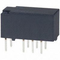
TXS2-24V
Description
RELAY 1A 24VDC 70MW PCB
Manufacturer
Panasonic Electric Works
Series
TX-Sr
Specifications of TXS2-24V
Relay Type
General Purpose
Circuit
DPDT (2 Form C)
Contact Rating @ Voltage
1A @ 30VDC
Coil Type
Standard
Coil Current
2.9mA
Coil Voltage
24VDC
Control On Voltage (max)
19.2 VDC
Control Off Voltage (min)
2.4 VDC
Mounting Type
Through Hole
Termination Style
PC Pin
Brand/series
TX-S Series
Contact Form
DPDT
Current, Rating
1 A
Diameter, Mounting
0.039 in. Dia. (Hole)
Dielectric Rating
1000 MW @ 500 VDC
Dimensions
0.591 in. L x 0.291 in. W x 0.323 in. H
Function
Sensitive
Latch Type
Single Side Stable
Material, Contact
Gold-Clad Silver Alloy
Number Of Pins
8
Power, Rating
30 W
Standards
UL, CSA
Temperature, Operating, Maximum
70 °C
Temperature, Operating, Minimum
-40 °C
Termination
Solder
Voltage, Control
24 VDC
Voltage, Rating
30 VDC
Lead Free Status / RoHS Status
Lead free / RoHS Compliant
Other names
255-2334-5
TXS2-24V
TXS2-24V
Available stocks
Company
Part Number
Manufacturer
Quantity
Price


2) 1 coil latching
3) 2 coil latching (L2, LT)
*Pulse drive (JIS C 5442-1986)
2. Specifications
Notes: *1 This value can change due to the switching frequency, environmental conditions, and desired reliability level, therefore it is recommended to check this with the
Contact
Rating
Electrical
characteristics
Mechanical
characteristics
Expected life
Conditions
Unit weight
Nominal coil
Nominal coil
Characteristics
1.5V DC
4.5V DC
1.5V DC
4.5V DC
12V DC
24V DC
12V DC
24V DC
voltage
voltage
3V DC
6V DC
9V DC
3V DC
6V DC
9V DC
*2 Refer to 6. Conditions for operation, transport and storage mentioned in AMBIENT ENVIRONMENT.
actual load. (AgPd contact type or SX relays are available for low level load switching [10V DC, 10mA max. level])
nominal voltage*
nominal voltage*
80%V or less of
80%V or less of
(at 20 C
(at 20 C
Arrangement
Initial contact resistance, max.
Contact material
Nominal switching capacity
Max. switching power
Max. switching voltage
Max. switching current
Min. switching capacity (Reference value)*
Nominal operating
power
Insulation resistance (Initial)
Breakdown voltage
(Initial)
Surge breakdown
voltage (Initial)
Temperature rise (at 20 C
Operate time [Set time] (at 20 C
Release time [Reset time] (at 20 C
Shock resistance
Vibration resistance
Mechanical
Electrical
Conditions for operation, transport and storage*
Max. operating speed (at rated load)
Set voltage
Set voltage
(Initial)
(Initial)
68
68
F)
F)
All Rights Reserved © COPYRIGHT Panasonic Electric Works Co., Ltd.
Single side stable
1 coil latching
2 coil latching
Between open contacts
Between contact and coil
Between contact sets
Between open contacts
Between contacts and coil
Functional
Destructive
Functional
Destructive
nominal voltage*
nominal voltage*
80%V or less of
80%V or less of
Item
(at 20 C
(at 20 C
Reset voltage
Reset voltage
68
(Initial)
(Initial)
F)
68
68
68
68
F)
F)
F)
F)
1
[ 10%] (at 20 C
[ 10%] (at 20 C
46.7mA
23.3mA
15.6mA
11.7mA
Set coil
2
7.8mA
5.8mA
6.3mA
Nominal operating
Nominal operating
23.3mA
11.7mA
current
current
7.8mA
5.8mA
3.9mA
2.9mA
2.1mA
2 Form C
Max. 100 m (By voltage drop 6 V DC 1A)
Standard contact: Ag+Au clad, AgPd contact (low level load): AgPd+Au clad (stationary),
AgPd (movable)
1 A 30 V DC (resistive load)
30 W (DC) (resistive load)
110V DC
1 A
10 A 10mV DC
50 mW (1.5 to 12 V DC), 70 mW (24 V DC)
35 mW (1.5 to 12 V DC), 50 mW (24 V DC)
70 mW (1.5 to 12 V DC), 150 mW (24 V DC)
Min. 1,000M
Measurement at same location as “Initial breakdown voltage” section.
750 Vrms for 1min. (Detection current: 10mA)
1,800 Vrms for 1min. (Detection current: 10mA)
1,000 Vrms for 1min. (Detection current: 10mA)
1,500 V (10 160 s) (FCC Part 68)
2,500 V (2 10 s) (Telcordia)
Max. 50 C
(By resistive method, nominal coil voltage applied to the coil; contact carrying current: 1A.)
Max. 5 ms [Max. 5 ms] (Nominal coil voltage applied to the coil, excluding contact bounce
time.)
Max. 5 ms [Max. 5 ms] (Nominal coil voltage applied to the coil, excluding contact bounce
time.) (without diode)
Min. 750 m/s
Min. 1,000 m/s
10 to 55 Hz at double amplitude of 3.3 mm (Detection time: 10 s.)
10 to 55 Hz at double amplitude of 5 mm
Min. 5 10
Min. 2 10
Ambient temperature: –40 C to +70 C
Humidity: 5 to 85% R.H. (Not freezing and condensing at low temperature)
20 cpm
Approx. 2 g
Reset coil
46.7mA
23.3mA
15.6mA
11.7mA
7.8mA
5.8mA
6.3mA
68
68
7
5
(at 180 cpm)
(1 A 30 V DC resistive) (at 20 cpm)
F)
F)
.071 oz
2
(Half-wave pulse of sine wave: 6 ms; detection time: 10 s.)
(at 500V DC)
2
(Half-wave pulse of sine wave: 6 ms.)
[ 10%] (at 20 C
[ 10%] (at 20 C
Set coil
1,157
2,057
3,840
32.1
129
289
514
Coil resistance
Coil resistance
11,520
1,029
2,314
4,114
64.3
257
579
Reset coil
1,157
2,057
3,840
32.1
129
289
514
68
68
F)
F)
Specifications
–40 F to +158
150mW
Set coil
70mW
Nominal operating
Nominal operating
35mW
50mW
power
power
F;
Reset coil
150mW
70mW
Max. applied voltage
Max. applied voltage
nominal voltage
nominal voltage
(at 20 C
(at 20 C
150%V of
150%V of
TX-S
68
68
F)
F)
Related parts for TXS2-24V
Image
Part Number
Description
Manufacturer
Datasheet
Request
R

Part Number:
Description:
RELAY LATCH 1A 12VDC 70MW PCB
Manufacturer:
Panasonic Electric Works
Datasheet:

Part Number:
Description:
RELAY TELCOM 1A DPDT 4.5VDC PCB
Manufacturer:
Panasonic Electric Works
Datasheet:
Part Number:
Description:
RELAY LATCH 1A 4.5VDC 70MW PCB
Manufacturer:
Panasonic Electric Works
Datasheet:
Part Number:
Description:
RELAY 1A 9VDC 50MW PCB
Manufacturer:
Panasonic Electric Works
Datasheet:
Part Number:
Description:
RELAY LATCH 1A 24VDC 150MW PCB
Manufacturer:
Panasonic Electric Works
Datasheet:
Part Number:
Description:
RELAY 1A 6VDC 50MW PCB
Manufacturer:
Panasonic Electric Works
Datasheet:
Part Number:
Description:
RELAY TELCOM 1A DPDT 12VDC PCB
Manufacturer:
Panasonic Electric Works
Datasheet:
Part Number:
Description:
RELAY 1A 3VDC 50MW PCB
Manufacturer:
Panasonic Electric Works
Datasheet:

Part Number:
Description:
RELAY 1A DPDT 4.5VDC SELF CLINCH
Manufacturer:
Panasonic Electric Works
Datasheet:

Part Number:
Description:
RELAY LATCH 1A DPDT 12VDC PCB
Manufacturer:
Panasonic Electric Works
Datasheet:

Part Number:
Description:
CONN SOCKET P4 .4MM 50POS SMD
Manufacturer:
Panasonic Electric Works
Datasheet:

Part Number:
Description:
CONN SOCKET .8MM 16POS SMD
Manufacturer:
Panasonic Electric Works
Datasheet:
Part Number:
Description:
CONN HEADER .8MM 16POS SMD
Manufacturer:
Panasonic Electric Works
Datasheet:
Part Number:
Description:
CONN SOCKET .8MM 20POS SMD
Manufacturer:
Panasonic Electric Works
Datasheet:
Part Number:
Description:
CONN SOCKET .8MM 20POS SMD
Manufacturer:
Panasonic Electric Works
Datasheet: