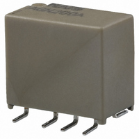
AGN200A4H Panasonic Electric Works, AGN200A4H Datasheet - Page 3

AGN200A4H
Manufacturer Part Number
AGN200A4H
Description
RELAY TELCOM DPDT 1A 4.5VDC SMD
Manufacturer
Panasonic Electric Works
Series
AGNr
Type
General Purpose Relayr
Specifications of AGN200A4H
Relay Type
Telecom
Circuit
DPDT (2 Form C)
Contact Rating @ Voltage
1A @ 30VDC
Coil Type
Standard
Coil Current
31mA
Coil Voltage
4.5VDC
Control On Voltage (max)
3.38 VDC
Control Off Voltage (min)
0.45 VDC
Mounting Type
Surface Mount
Termination Style
Gull Wing
Brand/series
AGN Series
Contact Form
DPDT
Current, Rating
1⁄0.3 AAC⁄ADC
Dimensions
0.417 in. +⁄- 0.012 in. L x 0.224 in. +⁄- 0.12 in. W x 0.354 in. +⁄- 0.12 in. H
Function
General Purpose
Latch Type
Single Side Stable
Material, Contact
AgPd + Au Clad (Stationary), AgPd (Movable)
Number Of Pins
8
Power, Rating
30 W
Standards
UL, CSA
Termination
Surface Mount
Voltage, Control
4.5 VDC
Voltage, Rating
125 VAC
Relay Construction
Non-Latching
Contact Arrangement
DPDT
Coil Voltage Dc
4.5V
Voltage Rating (vdc)
110V
Voltage Rating (vac)
125V
Dropout Volt (min)
0.45VDCV
Coil Resistance
145Ohm
Pick-up Voltage (max)
3.38VDC
Maximum Power Rating
30W/37.5VA
Operate Time
4ms
Contact Current Rating
1A
Contact Material
AgPd
Coil Suppression Diode
No
Push To Test Button
No
Led Indicator
No
Seal
Sealed
Product Height (mm)
10mm
Product Depth (mm)
7.4mm
Product Length (mm)
10.6mm
Operating Temp Range
-40C to 85C
Pin Count
8
Mounting Style
Surface Mount
Lead Free Status / RoHS Status
Lead free / RoHS Compliant
Other names
255-1233
255-1233-5
255-1233
255-1233-5
255-1233
Available stocks
Company
Part Number
Manufacturer
Quantity
Price
Company:
Part Number:
AGN200A4H
Manufacturer:
ELNA
Quantity:
20 000
Company:
Part Number:
AGN200A4HZ
Manufacturer:
YEONHO
Quantity:
9 613
Part Number:
AGN200A4HZ
Manufacturer:
NAIS
Quantity:
20 000
GN (AGN)
1) Standard packing: Tube: 50 pcs.; Case: 1,000 pcs.
2) Specified value of pick-up, drop-out, set and reset voltage is with the condition of square wave coil pulse.
DIMENSIONS
1. PC board terminal
2. Surface-mount terminal
1) A type
1) S type
REFERENCE DATA
1. Max. switching capacity
Operating
: For each surface-mounted terminal variation, input the following letter.
Function
latching
A type: A, S type: S
1 coil
1.0
0.3
AGN210 1H
AGN210 4H
Tube packing
AGN210 03
AGN210 06
AGN210 09
AGN210 12
AGN210 24
30
Tape and reel: 500 pcs.; Case: 1,000 pcs.
Contact voltage, V
.016 .004
Part No.
.016 .004
.016 .004
0.40 0.1
0.40 0.1
0.25 0.1
.010 .004
0.25 0.1
.010 .004
0.40 0.1
(1.50)
(.059)
DC resistive load
AC resistive load
(1.50)
(.059)
(1.50)
(.059)
AGN210 1HZ
AGN210 4HZ
AGN210 03Z
AGN210 06Z
AGN210 09Z
AGN210 12Z
AGN210 24Z
Tape and reel
100
packing
10.60 0.3
.417 .012
10.60 0.3
.417 .012
10.60 0.3
.417 .012
3.20 0.15
.126 .006
3.20 0.15
.126 .006
3.20 0.15
.126 .006
(0.50)
(.020)
2.20 0.15
.087 .006
(0.50)
(.020)
(0.50)
(.020)
2.20 0.15
.087 .006
2.20 0.15
.087 .006
9.00 0.3
.354 .012
Coil Rating,
9.00 0.3
.354 .012
9.00 0.3
.354 .012
2. Life curve
V DC
3.50 0.3
.138 .012
1.5
4.5
12
24
3
6
9
Max. 10.00
Max. 10.00
100
50
40
30
20
10
.394
0
.394
.224 .012
.291 .012
.224 .012
.224 .012
5.70 0.3
.224 .012
7.40 0.3
5.70 0.3
5.70 0.3
5.70 0.3
V DC (max.)
Set voltage,
0.2
(initial)
1.13
2.25
3.38
6.75
4.5
18
0.25 0.1
.010 .004
3.20 0.15
.126 .006
9
3.20 0.15
.126 .006
3.20 0.15
.126 .006
0.4
AC 125V
resistive load
Switching current, A
0.6
DC 30V resistive load
V DC (max.)
Suggested mounting pad
Suggested mounting pad
voltage,
(initial)
3.10
.122
0.8
Reset
Tolerance: 0.1
Tolerance: 0.1
Tolerance: 0.1
1.13
2.25
3.38
6.75
2.25
.089
4.5
18
3.20
.126
9
PC board pattern
3.20
.126
3.20
.126
8-0.85 dia.
8-.033 dia
1.0
7.60
.299
0.80
.031
1.2
0.80
.031
mA ( 10%)
operating
2.20
.087
Nominal
current,
2.20
.087
2.20
.087
66.7
33.3
22.2
16.7
11.1
8.3
5.0
3.20
.126
4.45
.175
.004
.004
.004
5.30
.209
(Deenergized condition)
(Deenergized condition)
resistance,
Single side stable
Single side stable
202.5
1,440
4,800
( 10%)
Direction indication
22.5
Direction indication
Coil
360
810
90
8
1
1
8
Schematic (Bottom view)
7 6 5
2 3 4
2 3 4
7 6 5
Schematic (Top view)
operating
Nominal
power,
mW
100
100
100
100
100
100
120
(Reset condition)
(Reset condition)
Direction indication
Direction indication
1 coil latching
1 coil latching
8
1
1
8
allowable
voltage,
V DC
2
7
7
2
Max.
2.25
6.75
13.5
4.5
mm
18
36
9
3
6
6
3 4
5
4
5
inch


