TQ2SA-5V-Z Panasonic Electric Works, TQ2SA-5V-Z Datasheet
TQ2SA-5V-Z
Specifications of TQ2SA-5V-Z
TQ2SA-5V-Z


Related parts for TQ2SA-5V-Z


TQ2SA-5V-Z Summary of contents
Page 1
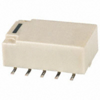
... Suitable for SMD automatic insertion (SA type) With a height of 5.6 mm .220 inch, the relays meet JIS C 0806 specifications. 4. High density mounting possible High-efficiency magnetic circuits ensure low magnetic flux leakage. Because characteristics are little changed by proximity mounting, high- density mounting is possible. ...
Page 2
TYPES Standard PC board terminal and self-clinching terminal 1. Standard (B.B.M.) type 1) Standard PC board terminal Single side stable Contact Nominal coil arrangement voltage Form 12V DC ...
Page 3
TQ 2) Self-clinching terminal Contact arrangement 2 Form C Standard packing: Tube: 50 pcs.; Case: 1,000 pcs. Notes: 1. Latching types are available by request. Please consult us for details. 2. UL/CSA approved (UL file No.:E 43149, CSA file No.: ...
Page 4
Form C) Nominal coil Set voltage voltage (at 20°C 68° 4. 75%V or less of 75%V or less nominal voltage* nominal voltage* (Initial 12V DC ...
Page 5
... This value can change due to the switching frequency, environmental conditions, and desired reliability level, therefore it is recommended to check this with the actual load. (SX relays are available for low level load switching [10V DC, 10mA max. level]) *3 Refer to “6. Usage, Storage and Transport Conditions” in Surface-mount terminal 1 ...
Page 6
... Notes: *1 This value can change due to the switching frequency, environmental conditions, and desired reliability level, therefore it is recommended to check this with the actual load. (SX relays are available for low level load switching [10V DC, 10mA max. level]) *2 Refer to “6. Usage, Storage and Transport Conditions” in ...
Page 7
TQ REFERENCE DATA Standard PC board terminal and self-clinching terminal 1. Maximum switching capacity DC load (cosϕ=1) AC load (cosϕ=1) 1.0 0.5 0.4 0.3 0.2 30 100 200 Switching voltage,V 4.-(1) Electrical life (DC load) Tested sample: TQ2-12V, 6 pcs. ...
Page 8
Influence of adjacent mounting Pick-up voltage 0 –10 ON OFF OFF 10 Drop-out voltage 0 OFF – .197 Inter-relay distance , mm inch 11. Actual load test ( wire spring ...
Page 9
... Max. 20 Min IRS 1 10 100 1,000 10,000 No. of operations, ×10 4 4.-(2) Electrical life (0.5 A 125 V AC resistive load) Tested sample: TQ2SA-12V, 6 pcs Operating speed: 20 cpm Change of pick-up and drop-out voltage (mounting by IRS method) 100 90 80 Pick-up voltage 70 Max. 60 Min Drop-out voltage Max ...
Page 10
... Single side stable 14 9 .551 .354 + − 0.5 0.25 .020 .010 2.54 7.62 .100 .300 Direction indication ±.012 (Deenergized condition) 10.-(2) Influence of adjacent mounting Tested sample: TQ2SA-12V, 6 pcs Pick-up voltage 0 –10 10 Drop-out voltage 0 – .039 .079 .118 .157 .197 ...
Page 11
Form C External dimensions Standard PC board terminal CAD Data (4.75) (.187) +0.4 5 −0.2 +.016 .197 −.008 3.5 .138 0.25 5.08 .010 .200 Self-clinching terminal (4.75) (.187) +0.4 5 −0.2 +.016 .197 −.008 3.5 .138 0.25 ...
Page 12
... TQ-SMD relays (10.1 .398)* Note) *SS type Tape coming out direction (2) Dimensions of plastic reel mm 21 dia. .827 dia. 2.0 .079 ±1 80 dia. ±.039 3.150 ±2 330 dia ...