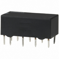
G6AK-234P-ST-US-DC5 Omron, G6AK-234P-ST-US-DC5 Datasheet

G6AK-234P-ST-US-DC5
Specifications of G6AK-234P-ST-US-DC5
Z749
Related parts for G6AK-234P-ST-US-DC5
G6AK-234P-ST-US-DC5 Summary of contents
Page 1
... DPDT 5. Terminals 4: 4PDT Ag + Au-Alloy G6A-274P-ST-US G6A-474P-ST-US G6A-274P-ST40-US G6A-474P-ST40- Au-Alloy G6AU-274P-ST-US G6AU-474P-ST- Au-Alloy G6AK-274P-ST-US G6AK-474P-ST-US G6AK-274P-ST40-US G6AK-474P-ST40-US Rated coil voltage - VDC Stand-off 7: Bifurcated crossbar ST: Stand-off 0. (Au-Alloy) contact 7. Special Function 40: Low-sensitivity (400 mW) 4: Fully sealed LT: Low thermoelectromotive force 8. Approved Standards P: Straight PCB US: UL, CSA certified 9 ...
Page 2
... Must operate voltage 70% max. of rated voltage Must release voltage 10% min. of rated voltage Max. voltage 150% of rated voltage at 23°C Power consumption Approx. 400 mW Low-sensitivity 4PDT Relays Rated voltage 3 VDC Rated current 133.3 mA 22.5 Ω Coil resistance Coil inductance Armature OFF ...
Page 3
... Set Armature OFF (H) (ref. value) Armature ON Reset Armature OFF Armature ON Must operate voltage Must release voltage Max. voltage Power consumption Double-winding Latching, 4PDT Relays Rated voltage Rated current Coil resistance Coil inductance Set Armature OFF (H) (ref. value) Armature ON Reset Armature OFF ...
Page 4
... L ms) 0 125 VAC; 0 125 VAC VDC VDC Ag (Au-Alloy 250 VAC, 220 VDC 125 VA 62 mVDC G6AK-274P-ST(40)-US/G6AK-474P-ST(40)-US G6AU-274P-ST-US/G6AU-474P-ST-US Resistive load Inductive load (cos φ (cos φ = 0.4; L ms) 0 125 VAC; 0. 125 VAC VDC VDC Ag (Au-Alloy 250 VAC, 220 VDC ...
Page 5
... UL114, UL478 (File No. E41515)/CSA C22.2 No.0, No.14 (File No. LR31928) Model G6A-274P-ST(40)-US DPDT G6AK-274P-ST(40)-US G6AU-274P-ST-US G6A-474P-ST(40)-US 4PDT G6AK-474P-ST(40)-US G6AU-474P-ST-US DPDT max. (approx. 3 ms) 4PDT max. (approx. 3.8 ms) DPDT max. (approx. 2.5 ms) 4PDT max. (approx.approx. 3.3 ms) DPDT max. (approx. 1.2 ms) 4PDT max. (approx. 1.3 ms) DPDT max ...
Page 6
G6A Engineering Data Maximum Switching Power DPDT, 4PDT DC inductive (L ms) DC resistive AC resistive AC inductive (cosf = 0.4) Switching voltage (V) Endurance DPDT 100 -274P 30 VDC, resistive 50 -234P 30 VDC, resistive; 20 -274P ...
Page 7
... G6A Dimensions Note: 1. All units are in millimeters unless otherwise indicated. 2. Orientation marks are indicated as follows: G6A-274P-ST(40)-US 20.2 max. (20)* 0.6 *Average value G6A-474P-ST-US 0.6 G6AK-274P-ST(40)-US 20.2 max. (20)* 0.6 *Average value Terminal Arrangement/ Internal Connections (Bottom View) 10.1 max. (9.9 8.4 max. 0.64 (8 ...
Page 8
... G6A G6AK-474P-ST(40)-US 0.6 G6AU-274P-ST-US 20.2 max. (20)* 0.6 *Average value G6AU-474P-ST-US 0.6 116 10.1 max. (9.9)* 35.4 max. (35.2)* 8.4 max. 0.64 (8.2)* 0.3 3.16 7.62 *Average value Sixteen, 1.0-dia. holes Terminal Arrangement/ Internal Connections (Bottom View) 10.1 max. (9.9)* 8.4 max. ...
Page 9
G6A Precautions Long-term Continuously ON Contacts Using the Relay in a circuit where the Relay will be ON continu- ously for long periods (without switching) can lead to unstable contacts because the heat generated by the coil itself will affect ...


