DS1E-ML2-DC12V Panasonic Electric Works, DS1E-ML2-DC12V Datasheet - Page 3
DS1E-ML2-DC12V
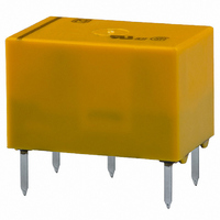
Manufacturer Part Number
DS1E-ML2-DC12V
Description
RELAY MINI LATCHING 12VDC PCB
Manufacturer
Panasonic Electric Works
Series
DSr
Type
General Purpose Relayr
Datasheet
1.DS2E-M-DC24V.pdf
(6 pages)
Specifications of DS1E-ML2-DC12V
Relay Type
General Purpose
Circuit
SPDT (1 Form C)
Contact Rating @ Voltage
2A @ 30VDC
Coil Type
Latching, Dual Coil
Coil Current
30mA
Coil Voltage
12VDC
Control On Voltage (max)
8.4 VDC
Mounting Type
Through Hole
Termination Style
PC Pin
Relay Construction
Latching Double Coil
Contact Arrangement
SPDT
Coil Voltage Dc
12V
Contact Form
1 Form C
Voltage Rating (vdc)
220V
Voltage Rating (vac)
250V
Coil Resistance
400Ohm
Pick-up Voltage (max)
8.4VDC
Maximum Power Rating
60W/125VA
Operate Time
10ms
Contact Current Rating
3A
Contact Material
Ag/Au Clad
Coil Suppression Diode
No
Push To Test Button
No
Led Indicator
No
Seal
Sealed
Product Height (mm)
9.9mm
Product Depth (mm)
9.9mm
Product Length (mm)
15mm
Operating Temp Range
-40C to 70C
Pin Count
6
Mounting Style
Through Hole
Package / Case
DIP
Lead Free Status / RoHS Status
Lead free / RoHS Compliant
Control Off Voltage (min)
-
Lead Free Status / Rohs Status
Compliant
Other names
255-1475
DS1E-ML2-DC12V
DS1E-ML2-DC12V
Available stocks
Company
Part Number
Manufacturer
Quantity
Price
Company:

Part Number:
DS1E-ML2-DC12V
Manufacturer:
PANASONIC
Quantity:
3 400
Company:
Part Number:
DS1E-ML2-DC12V
Manufacturer:
Panasonic Electric Works
Quantity:
1 971
Part Number:
DS1E-ML2-DC12V
Manufacturer:
PANASONIC/松下
Quantity:
20 000


2) 2 coil latching type
2. Specifications
Notes: *1 This value can change due to the switching frequency, environmental conditions, and desired reliability level, therefore it is recommended to check this with the
Contact
Rating
Electrical
characteristics
Mechanical
characteristics
Expected life
Conditions
Unit weight
sensitivity
Standard
(M) type
(S) type
Characteristics
Type
High
*2 Half-wave pulse of sine wave: 11ms; detection time: 10µs
*3 Refer to 6. Conditions for operation, transport and storage mentioned in AMBIENT ENVIRONMENT.
actual load.
(SX relays are available for low level load switching [10V DC, 10mA max. level])
Nominal coil
1.5V DC
1.5V DC
12V DC
24V DC
48V DC
12V DC
24V DC
48V DC
voltage
3V DC
5V DC
6V DC
9V DC
3V DC
5V DC
6V DC
9V DC
Arrangement
Initial contact resistance, max.
Contact material
Nominal switching capacity
Max. switching power
Max. switching voltage
Max. carrying current
Min. switching capacity (Reference value)*
Nominal operating power
Insulation resistance (Initial)
Breakdown voltage
(Initial)
Temperature rise
Operate time [Set time] (at 20°C 68°F)
Release time [Reset time] (at 20°C 68°F)
Shock resistance
Vibration resistance
Mechanical
Electrical
Conditions for operation, transport and storage*
Max. operating speed (at rated load)
70%V or less of
nominal voltage
80%V or less of
nominal voltage
70%V or less of
nominal voltage
(at 20°C 68°F)
Set voltage
1 Form C:
2 Form C:
(Initial)
(Initial)
All Rights Reserved © COPYRIGHT Panasonic Electric Works Co., Ltd.
Between open contacts
Between contact and coil
Functional*
Destructive
Functional
Destructive
Item
70%V or less of
nominal voltage
80%V or less of
nominal voltage
70%V or less of
nominal voltage
(at 20°C 68°F)
Reset voltage
2
1 Form C:
2 Form C:
(Initial)
(Initial)
1
3
3.75mA
Set coil
240mA
120mA
120mA
7.5mA
7.5mA
Nominal operating
Max. 10 ms [10 ms] (Nominal coil voltage applied to the coil, excluding contact bounce time.)
72mA
60mA
40mA
30mA
15mA
60mA
36mA
30mA
20mA
15mA
Max. 5 ms [10 ms] (Nominal coil voltage applied to the coil, excluding contact bounce time.)
(By resistive method, nominal coil voltage applied to the coil, contact carrying current: 2A.)
current [±10%]
(at 20°C 68°F)
(1,000 Vrms for 1min: 1 Form C high sensitivity type) (Detection current: 10mA.)
(500 Vrms for 1min: 1 Form C high sensitivity type) (Detection current: 10mA.)
Humidity: 5 to 85% R.H. (Not freezing and condensing at low temperature)
Reset coil
3.75mA
Measurement at same location as “Initial breakdown voltage” section.
240mA
120mA
120mA
7.5mA
7.5mA
72mA
60mA
40mA
30mA
15mA
60mA
36mA
30mA
20mA
15mA
10 to 55 Hz at double amplitude of 3.3 mm (Detection time: 10µs.)
Approx. 3 g
Min. 490 m/s
1 Form C
Ambient temperature: –40°C to +70°C
Single side stable (M type: 400 mW, S type: 200 mW);
Min. 980 m/s
Min. 10
12,800Ω
Set coil
1,600Ω
6,400Ω
3,200Ω
6.25Ω
69.4Ω
12.5Ω
latching (M type: 360 mW, S type: 180 mW)
100Ω
225Ω
400Ω
139Ω
200Ω
450Ω
800Ω
25Ω
50Ω
Max. 50 mΩ (By voltage drop 6 V DC 1A)
.11 oz
Coil resistance
10 to 55 Hz at double amplitude of 5 mm
(at 20°C 68°F)
8
2
(10
Min. 5×10
[±10%]
60 W, 125 VA (resistive load)
2 A 30 V DC (resistive load)
7
Min. 100MΩ (at 500V DC)
2
: 1 Form C latching type) (at 600 cpm)
Reset coil
(Half-wave pulse of sine wave: 6 ms.)
12,800Ω
1,600Ω
6,400Ω
3,200Ω
1,000 Vrms for 1min.
1,500 Vrms for 1min.
220 V DC, 250 V AC
6.25Ω
69.4Ω
12.5Ω
100Ω
225Ω
400Ω
139Ω
200Ω
450Ω
800Ω
25Ω
50Ω
10µA 10m V DC
(without diode)
Specifications
5
Ag+Au clad
rated load (at 60 cpm)
Max. 65°C
60 cpm
3 A
360mW
Set coil
180mW
Nominal operating
power
–40°F to +158°F
Reset coil
360mW
180mW
Approx. 4g
Min. 490 m/s
2 Form C
Max. applied voltage
.14oz
(at 50°C 122°F)
nominal voltage
nominal voltage
nominal voltage
nominal voltage
2
1 Form C:
2 Form C:
1 Form C:
2 Form C:
120%V of
150%V of
160%V of
200%V of
DS
Related parts for DS1E-ML2-DC12V
Image
Part Number
Description
Manufacturer
Datasheet
Request
R

Part Number:
Description:
RELAY MINI LATCHING 5VDC PCB
Manufacturer:
Panasonic Electric Works
Datasheet:
Part Number:
Description:
RELAY MINI 6VDC 360MW DIP
Manufacturer:
Panasonic Electric Works
Datasheet:
Part Number:
Description:
RELAY MINI LATCHING 3VDC PCB
Manufacturer:
Panasonic Electric Works
Datasheet:
Part Number:
Description:
RELAY LATCHING 3VDC PC MNT
Manufacturer:
Panasonic Electric Works
Datasheet:
Part Number:
Description:
RELAY MINI 2-LATCH 9VDC DIP
Manufacturer:
Panasonic Electric Works
Datasheet:
Part Number:
Description:
RELAY MINI LATCHING 24VDC PCB
Manufacturer:
Panasonic Electric Works
Datasheet:
Part Number:
Description:
RELAY MINI 2-LATCH 48VDC DIP
Manufacturer:
Panasonic Electric Works
Datasheet:
Part Number:
Description:
RELAY MINI 48VDC 400MW DIP
Manufacturer:
Panasonic Electric Works
Datasheet:
Part Number:
Description:
RELAY MINI 12VDC 400MW DIP
Manufacturer:
Panasonic Electric Works
Datasheet:
Part Number:
Description:
RELAY MINI 400MW 5VDC PCB
Manufacturer:
Panasonic Electric Works
Datasheet:

Part Number:
Description:
CONN SOCKET P4 .4MM 50POS SMD
Manufacturer:
Panasonic Electric Works
Datasheet:

Part Number:
Description:
CONN SOCKET .8MM 16POS SMD
Manufacturer:
Panasonic Electric Works
Datasheet:
Part Number:
Description:
CONN HEADER .8MM 16POS SMD
Manufacturer:
Panasonic Electric Works
Datasheet:
Part Number:
Description:
CONN SOCKET .8MM 20POS SMD
Manufacturer:
Panasonic Electric Works
Datasheet:
Part Number:
Description:
CONN SOCKET .8MM 20POS SMD
Manufacturer:
Panasonic Electric Works
Datasheet: