ST2-DC5V Panasonic Electric Works, ST2-DC5V Datasheet - Page 3
ST2-DC5V
Manufacturer Part Number
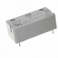
ST2-DC5V
Description
RELAY PWR DPST-NO 8A 5V PC MNT
Manufacturer
Panasonic Electric Works
Series
STr
Specifications of ST2-DC5V
Relay Type
General Purpose
Contact Form
DPST (2 Form A)
Contact Rating (current)
8A
Switching Voltage
380VAC
Coil Type
Standard
Coil Current
47.6mA
Coil Voltage
5VDC
Turn On Voltage (max)
4 VDC
Turn Off Voltage (min)
0.5 VDC
Mounting Type
Through Hole
Termination Style
PC Pin
Circuit
DPST (2 Form A)
Contact Rating @ Voltage
8A @ 380VAC
Control On Voltage (max)
4 VDC
Control Off Voltage (min)
0.5 VDC
Brand/series
ST Series
Current, Rating
8 A
Diameter, Mounting
0.055 in. Dia. (Hole)
Dimensions
1.220 in. L x 0.551 in. W x 0.445 in. H
Function
General Purpose
Latch Type
Single Side Stable
Material, Contact
Gold Flash Over Silver Alloy
Number Of Pins
6
Standards
UL, CSA, VDE
Termination
Solder
Voltage, Control
5 VDC
Voltage, Rating
380 VAC
Lead Free Status / RoHS Status
Lead free / RoHS Compliant
Other names
255-1291
Available stocks
Company
Part Number
Manufacturer
Quantity
Price

Part Number:
ST2-DC5V
Manufacturer:
NAIS
Quantity:
20 000
Company:
Part Number:
ST2-DC5V-F
Manufacturer:
NAIS/PANASONIC
Quantity:
20 000
Part Number:
ST2-DC5V-Z1
Manufacturer:
PANASONIC/松下
Quantity:
20 000


ST
4. Influence of adjacent mounting
Sample: ST1-DC24V
ST relay socket
DIMENSIONS
Precautions for use (socket)
1. PC board mounting method
PC board pattern
The terminal configuration is symmetrical
on the left and right, so an arrow mark ;
is stamped on the socket to prevent mis-
insertion. We recommend printing the
same arrow mark ; on the component
mounting side (side opposite from
pattern) of the PC board. In this case, the
terminal configuration becomes the
terminal nos. noted near the drilling
holes.
2. Chassis cutout
Chassis cutting dimensions
Contact
terminal
interval
Coil
terminal
interval
Solder terminal socket
–10
–20
20
10
0
8-.060 DIA.
8-1.5 DIA.
8
1
ST-SS
5
7
2
(1) & (3) relays are energized.
Inter-relay distance, mm
10
Drop-out
Pick-up
7.62
.300
8
1
6
3
15
(1)
ST-PS
7
2
10.16
1.244
1.394
.400
31.6
35.4
5
4
20
(2)
2.54
.100
(3)
6
3
7.62
.300
PC board terminal socket
1.05
.041
2.54
.100
5
4
16.6
.654
.012
.169
0.3
4.3
ST-PS
5. Max. ambient temperature by operating
power
If the chassis hole is punched with a
press, set so the release R on the front
side (A side).
The range for chassis thickness is 0.6 to
2.2 mm
3. Relay mounting and removal
(1) Align the directions of the relay and socket.
0.27
.011
A side
120
110
100
10.16
90
80
70
60
50
40
30
20
10
.400
14.6
.575
0
.024 to .087
0.2 0.4 0.6 0.8 1.0 1.2 1.4 1.6 1.8 2.0 2.2 2.4
.158
1.280±.004
.217
5.5
32.5±0.1
4
Press
16.4
.646
8 A carrying
Operating power, mW
Relay
inch.
Specifications
Breakdown voltage
Insulation resistance
Heat resistance
Max. continuous current
Relay insertion life
Chassis t = 0.6 to 2.2
.591±.008
15.0±0.2
No load
Claw for chassis
fastening
8
1
7.62
.300
.024 to .087
ST-SS
7
2
10.16
1.244
1.394
.400
31.6
35.4
.090
6
3
7.62
.300
2.3
5
4
6. Contact reliability
(2) Insert the relay all the way in, so it is
securely in place.
(3) Press the part indicated by A in the B
direction, and fasten by placing the hook on the
relay.
(4). When removing the relay, completely
release the hooks on both sides and pull the
relay out.
(%)
95.0
80.0
60.0
40.0
25.0
15.0
.012
.209
16.6
.654
0.3
5.3
0.15
cross-section
More than 1,000 MΩ between terminals
4.0
1.5
0.4
0.27
.011
Relay case
70.0
10.0
99.9
99.8
99.0
90.0
50.0
30.0
20.0
5.0
3.0
2.0
1.0
0.5
0.3
0.2
0.1
2,000 Vrms Contacts/Contacts
0.1
250 V AC
(Before fastening)
4,000 Vrms Coil/Contacts
10.16
.400
14.6
.575
150°C (302°F) for 1 hr
0.2 0.3 0.5 0.7 0.9
ST-Relay
250 V AC cos ϕ = 1.0
0.33 Hz
10 A
m = 3.9
η = 16.8×10
ρ
0.95
0.4 0.6 0.8 1.0
= 7.7×10
15 times
.158
No. of operations, ×10
.217
5.5
4
10 A
16.4
.646
4
A
4
8 A
m = 3.5
η = 3.3×10
ρ
(Fastening complete)
.
0.95
.
Hinge
mechanism
2.0 3.0 5.07.0 9.0
= 1.4×10
5
5
5
mm
inch
Related parts for ST2-DC5V
Image
Part Number
Description
Manufacturer
Datasheet
Request
R

Part Number:
Description:
RELAY POWER DPST-NO 8A 24V PCB
Manufacturer:
Panasonic Electric Works
Datasheet:

Part Number:
Description:
RELAY POWER DPST-NO 8A 12V PCB
Manufacturer:
Panasonic Electric Works
Datasheet:
Part Number:
Description:
RELAY POWER LATCH 8A 5VDC PCB
Manufacturer:
Panasonic Electric Works
Datasheet:

Part Number:
Description:
RELAY PWR DPST 8A 5VDC PC MNT
Manufacturer:
Panasonic Electric Works
Datasheet:
Part Number:
Description:
RELAY POWER LATCH 8A 5VDC PCB
Manufacturer:
Panasonic Electric Works
Datasheet:
Part Number:
Description:
RELAY POWER DPST 8A 9VDC PCB
Manufacturer:
Panasonic Electric Works
Datasheet:
Part Number:
Description:
RELAY POWER DPST 8A 48VDC PCB
Manufacturer:
Panasonic Electric Works
Datasheet:

Part Number:
Description:
RELAY PWR DPST-NO 8A 12V PC MNT
Manufacturer:
Panasonic Electric Works
Datasheet:

Part Number:
Description:
RELAY PWR DPST-NO 8A 24V PC MNT
Manufacturer:
Panasonic Electric Works
Datasheet:
Part Number:
Description:
RELAY POWER 8A 3VDC PCB
Manufacturer:
Panasonic Electric Works
Datasheet:

Part Number:
Description:
CONN SOCKET P4 .4MM 50POS SMD
Manufacturer:
Panasonic Electric Works
Datasheet:
Part Number:
Description:
CONN SOCKET .8MM 16POS SMD
Manufacturer:
Panasonic Electric Works
Datasheet:
Part Number:
Description:
CONN HEADER .8MM 16POS SMD
Manufacturer:
Panasonic Electric Works
Datasheet:
Part Number:
Description:
CONN SOCKET .8MM 20POS SMD
Manufacturer:
Panasonic Electric Works
Datasheet:
Part Number:
Description:
CONN SOCKET .8MM 20POS SMD
Manufacturer:
Panasonic Electric Works
Datasheet: