G2R-1-SN-DC24 Omron, G2R-1-SN-DC24 Datasheet - Page 24
G2R-1-SN-DC24
Manufacturer Part Number
G2R-1-SN-DC24
Description
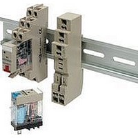
RELAY PWR SPDT 10A 24VDC QC MNT
Manufacturer
Omron
Series
G2RSr
Datasheets
1.G2R-1A-E-DC12.pdf
(30 pages)
2.G2R-1A-E-DC12.pdf
(14 pages)
3.G2R-1-S_DC12S.pdf
(12 pages)
Specifications of G2R-1-SN-DC24
Relay Type
General Purpose
Contact Form
SPDT (1 Form C)
Contact Rating (current)
10A
Switching Voltage
440VAC, 125VDC - Max
Coil Type
Standard
Coil Current
21.6mA
Coil Voltage
24VDC
Turn On Voltage (max)
16.8 VDC
Turn Off Voltage (min)
3.6 VDC
Mounting Type
Socket
Termination Style
Quick Connect - .187" (4.7mm)
Circuit
SPDT (1 Form C)
Contact Rating @ Voltage
10A @ 250VAC
Control On Voltage (max)
16.8 VDC
Control Off Voltage (min)
3.6 VDC
Coil Voltage Vdc Nom
24V
Coil Resistance
1100ohm
Contact Configuration
SPDT
Relay Mounting
Plug In
Peak Reflow Compatible (260 C)
No
Leaded Process Compatible
No
Contact Current Max
10A
Contact Voltage Ac Nom
250V
Contact Voltage Dc Nom
30V
Rohs Compliant
Yes
Lead Free Status / RoHS Status
Contains lead / RoHS non-compliant
Other names
G2R1SNDC24
Available stocks
Company
Part Number
Manufacturer
Quantity
Price
Company:

Part Number:
G2R-1-SN-DC24V
Manufacturer:
OMRON
Quantity:
12 000


■ Driving by IC
An IC on which multiple driving transistors are integrated is available.
The designing of the circuit or PCB to drive multiple relays, a small-
size solenoid, or a small-size lamp can be simplified by using this IC.
Consult the manufacturer of the IC for details. For V
description of the related voltage and surge suppressor.
Dimensions Connection (Top view)
Equivalent circuit
■ Driving by TTL
TTLs can be divided into two types by classification of the output:
totem-pole and open-collector outputs. Connection of each type of
TTL is described below.
Use a diode as surge suppressor.
In the specifications of some ICs, such a phrase as “fan-out 10” may
be used in place of the legend I
TTLs can be connected in parallel. In terms of current, fan-out 1
equals 1.6 mA. Hence,
Fan-out n = 1.6 x n (mA)
1. To drive a relay by the totem-pole output of a TTL, these condi-
24
tions must be satisfied:
• I
• I
• Minimum supply voltage (4.75 V) – Maximum V
resistance.
(%)/Coil resistance
put voltage) > Lower-limit value of pickup voltage (Refer to Driv-
ing by Transistor)
OL
OH
(high-level output current) < Rated current x pickup voltage
(low-level output current) > Maximum supply voltage/Coil
Electromechanical Relays
GND
OL
. This denotes that 10 standard
I: Input (Base)
O: Output (Collector)
GND: (Common Emitter)
Technical Information
OL
GND
CE
(low-level out-
, refer to the
Totem-pole output
2. To drive a relay with open-collector output type TTL, a degree of
Open-collector output
The above description of the standard TTL is applicable when using
S, H, and LS type TTLs.
■ Driving by Other Switching
Consult the manufacturer of the switching device. The upper- and
lower-limit values of the pickup voltage can be determined in the
same manner as described in Upper-limit Pickup Voltage and Lower-
limit Pickup Voltage.
Example of Driving by SCR
freedom is allowed in the ratings of the relay coil. However, these,
conditions must be satisfied:
• I
• I
• V
• V
Devices
by Transistor.)
to Driving by Transistor.)
OL
OH
O
OL
> Maximum supply voltage to the relay coil/Coil resistance
= Dielectric strength of the output transistor (Refer to Driving
< Rated current x pickup voltage (%)/200
= Collector emitter voltage V
CE
of the output transistor (Refer
Related parts for G2R-1-SN-DC24
Image
Part Number
Description
Manufacturer
Datasheet
Request
R

Part Number:
Description:
RELAY SPDT 24VDC PLUG-IN W/LED
Manufacturer:
Omron
Datasheet:
Part Number:
Description:
RELAY SPDT 12VDC PLUG-IN W/LED
Manufacturer:
Omron
Datasheet:

Part Number:
Description:
RELAY SPDT 120VAC PLUG-IN W/LED
Manufacturer:
Omron
Datasheet:
Part Number:
Description:
RELAY SPDT 6VDC PLUG-IN W/LED
Manufacturer:
Omron
Datasheet:
Part Number:
Description:
RELAY SPDT 24VAC PLUG-IN W/LED
Manufacturer:
Omron
Datasheet:

Part Number:
Description:
RELAY SPDT 5VDC PLUG-IN W/LED
Manufacturer:
Omron
Datasheet:

Part Number:
Description:
RELAY SPDT 110VAC PLUG-IN W/LED
Manufacturer:
Omron
Datasheet:
Part Number:
Description:
RELAY SPDT 200/220V PLUGIN W/LED
Manufacturer:
Omron
Datasheet:
Part Number:
Description:
RELAY SPDT 240VAC PLUG-IN W/LED
Manufacturer:
Omron
Datasheet:
Part Number:
Description:
Relay
Manufacturer:
Omron
Datasheet:


Part Number:
Description:
RELAY
Manufacturer:
Omron
Datasheet:
Part Number:
Description:
RELAY
Manufacturer:
Omron
Datasheet:
Part Number:
Description:
RELAYS
Manufacturer:
Omron
Datasheet: