HG2-DC24V-F Panasonic Electric Works, HG2-DC24V-F Datasheet - Page 9
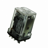
HG2-DC24V-F
Manufacturer Part Number
HG2-DC24V-F
Description
RELAY PWR CUBE DPDT 20A 24VDC
Manufacturer
Panasonic Electric Works
Series
HGr
Type
Power Relayr
Specifications of HG2-DC24V-F
Relay Type
General Purpose
Contact Form
DPDT (2 Form C)
Contact Rating (current)
20A
Switching Voltage
250VAC
Coil Type
Standard
Coil Current
57.6mA
Coil Voltage
24VDC
Turn On Voltage (max)
19.2 VDC
Turn Off Voltage (min)
2.4 VDC
Mounting Type
Socket
Termination Style
Quick Connect - .250" (6.3mm)
Circuit
DPDT (2 Form C)
Contact Rating @ Voltage
20A @ 250VAC
Control On Voltage (max)
19.2 VDC
Control Off Voltage (min)
2.4 VDC
Relay Construction
Non-Latching
Contact Arrangement
DPDT
Coil Voltage Dc
24V
Voltage Rating (vac)
250V
Dropout Volt (min)
2.4VDCV
Coil Resistance
416Ohm
Pick-up Voltage (max)
19.2VDC
Operate Time
30ms
Contact Current Rating
20A
Coil Suppression Diode
No
Push To Test Button
No
Led Indicator
No
Seal
Unsealed
Product Depth (mm)
36mm
Product Length (mm)
34mm
Operating Temp Range
-50C to 40C
Pin Count
8
Mounting Style
Socket
Package / Case
Dust Cover
Lead Free Status / RoHS Status
Lead free / RoHS Compliant
Other names
255-2785


With 4-pole HG relays, use two HG2-DIN rail terminal sockets side by side.
OTHER WAYS TO MOUNT RELAYS
With direct mounting by cover tapping
(Tab terminal connection)
Compatible with #250 series
DIL RAIL TERMINAL SOCKET (SOCKET) COMBINATION
Because the pole numbers of the terminal sockets (sockets) are interchangeable,
different terminal sockets (sockets) can be used in combination.
NOTES
1. Hold-down clip
Please use the hold-down clip whenever
HG relays will be used in applications
where strong vibrating or shock force
occurs.
2. Mounting direction
There is no restriction on the mounting
direction. However, if the mounted relay
will be susceptible to strong vibrations or
shocks, to avoid influence on switching
operations, mount so that the direction of
vibration and shock are not in line with
HG2 main unit + HG2 main unit + HG2 main unit
HG2
HG2
HG4
HG2
(Dimension A)
Mounting hole diagram
Schematic for terminal socket and relay
HG2
HG2: 15mm
HG3: 17mm
HG4: 34mm
All Rights Reserved © COPYRIGHT Panasonic Electric Works Co., Ltd.
4
3
HG3 terminal socket + HG3 terminal socket
2
4
1
1
3
2
5
.591inch
.669inch
1.339inch
(TOP VIEW)
8
6
7
5
12
11
the direction of contact switching. (In
direction of contact switching operation,
resistance to external shock is more than
98 m/s
is likely to be susceptible to strong
vibrations or shocks, be sure to fit the
hold-down clip.
3. Environment
Avoid use in adverse conditions, such as
where there is exposure to harmful gas,
or where ambient temperatures are high
(more than 40 C
14
6
15
4
1
3
2
2
5
). Moreover, if the mounted relay
8
6
7
7
10
9
8
Note: The plain numbers
104
denote the terminal
socket terminal
number. The white
numbers in black
circles denote the
relay terminal
number.
F).
HG4 main unit
HG3 main unit + HG3 main unit
HG3
HG2 terminal socket + HG2 terminal socket
HG RELAY ACCESSORIES
Note: Hold-down clip is packaged with the terminal socket.
HG4
HG3
HG2 terminal socket + HG2 terminal socket + HG2 terminal socket
4. Do not insert or remove relays into
or out of live circuits.
5. To prevent damage or distortion,
when tightening fixing screws of
terminal socket, the optimum torque
range should be 1.176 to 1.37 N·m (12
to 14 kgf·cm).
With a relay mounted
Related parts for HG2-DC24V-F
Image
Part Number
Description
Manufacturer
Datasheet
Request
R

Part Number:
Description:
SOCKET W/CLIP SCRW DIN HG2 RELAY
Manufacturer:
Panasonic Electric Works

Part Number:
Description:
RELAY PWR DPDT 20A 12VDC PLUG-IN
Manufacturer:
Panasonic Electric Works
Datasheet:
Part Number:
Description:
SOCKET W/CLIP SLD FOR HG2 RELAY
Manufacturer:
Panasonic Electric Works
Datasheet:
Part Number:
Description:
SOCKET DIRECT MNT FOR HG2 RELAY
Manufacturer:
Panasonic Electric Works
Datasheet:

Part Number:
Description:
HG2 Relay (Plug-in)
Manufacturer:
PANASONIC EW
Datasheet:
Part Number:
Description:
HG2 Relay (Cd-Free)
Manufacturer:
PANASONIC EW
Datasheet:

Part Number:
Description:
Relay Sockets & Hardware W/CLIP FOR HG2 RELAY
Manufacturer:
Panasonic
Datasheet:

Part Number:
Description:
RELAY PWR DPDT 20A 12VDC PLUG-IN
Manufacturer:
Panasonic Electric Works
Datasheet:
Part Number:
Description:
RELAY CUBE 115VAC 20A
Manufacturer:
Panasonic Electric Works
Datasheet:

Part Number:
Description:
CONN SOCKET P4 .4MM 50POS SMD
Manufacturer:
Panasonic Electric Works
Datasheet:
Part Number:
Description:
CONN SOCKET .8MM 16POS SMD
Manufacturer:
Panasonic Electric Works
Datasheet:
Part Number:
Description:
CONN HEADER .8MM 16POS SMD
Manufacturer:
Panasonic Electric Works
Datasheet:
Part Number:
Description:
CONN SOCKET .8MM 20POS SMD
Manufacturer:
Panasonic Electric Works
Datasheet:
Part Number:
Description:
CONN SOCKET .8MM 20POS SMD
Manufacturer:
Panasonic Electric Works
Datasheet: