DSP1-DC9V-F Panasonic Electric Works, DSP1-DC9V-F Datasheet - Page 4
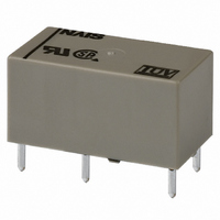
DSP1-DC9V-F
Manufacturer Part Number
DSP1-DC9V-F
Description
RELAY PWR DPST 5A 9VDC PCB
Manufacturer
Panasonic Electric Works
Series
DSPr
Type
Miniature Power Relayr
Datasheet
1.DSP1A-DC9V.pdf
(7 pages)
Specifications of DSP1-DC9V-F
Relay Type
General Purpose
Contact Form
DPST-NO/NC (1 Form A and B)
Contact Rating (current)
5A
Switching Voltage
250VAC
Coil Type
Standard
Coil Current
33.3mA
Coil Voltage
9VDC
Turn On Voltage (max)
7.2 VDC
Turn Off Voltage (min)
0.9 VDC
Mounting Type
Through Hole
Termination Style
PC Pin
Circuit
DPST-NO/NC (1 Form A and B)
Contact Rating @ Voltage
5A @ 250VAC
Control On Voltage (max)
7.2 VDC
Control Off Voltage (min)
0.9 VDC
Relay Construction
Non-Latching
Contact Arrangement
SPST-NO/SPST-NC
Coil Voltage Dc
9V
Voltage Rating (vdc)
30V
Voltage Rating (vac)
250V
Dropout Volt (min)
0.9VDCV
Coil Resistance
270Ohm
Pick-up Voltage (max)
7.2VDC
Maximum Power Rating
150W/1.25KVA
Operate Time
10ms
Contact Current Rating
5A
Contact Material
Silver Tin Oxide/Gold Flash
Coil Suppression Diode
No
Push To Test Button
No
Led Indicator
No
Seal
Sealed
Product Height (mm)
10.5mm
Product Depth (mm)
11mm
Product Length (mm)
20.2mm
Operating Temp Range
-40C to 65C
Pin Count
6
Mounting Style
Through Hole
Package / Case
DIP
Lead Free Status / RoHS Status
Lead free / RoHS Compliant
Other names
255-2966
DSP1-DC9V-F
DSP1-DC9V-F


DSP
4.-(1) Operate & release time
(without diode, 1 Form A)
Tested sample: DSP1a-DC12V, 5 pcs.
4.-(4) Operate & release time
(with diode, 1 Form A)
Tested sample: DSP1a-DC12V, 5 pcs.
5.-(1) Change of pick-up and drop-out voltage
(1 Form A)
Tested sample: DSP1a-DC12V, 5 pcs.
6.-(1) Influence of adjacent mounting
(1 Form A)
Tested sample: DSP1a-DC12V, 5 pcs.
15
10
15
10
9
8
7
6
5
4
3
2
1
0
5
5
7
6
5
4
3
2
1
0
0
–40 –20
80
80
Pick-up voltage
Drop-out voltage
Coil applied voltage, %V
Coil applied voltage, %V
Inter-relay distance ( ), mm
0
5
Release time
100
100
–50
50
20 40
Operate time
Operate time
Release time
Pick-up voltage
60
Ambient
temperature, C
10
A, C
relays
are not
energized
A, C
relays
are
energized
A
Drop-out
voltage
120
80
120
B
Max.
x
Min.
Max.
x
Min.
Max.
x
Min.
Max.
x
Min.
C
All Rights Reserved © COPYRIGHT Panasonic Electric Works Co., Ltd.
4.-(2) Operate & release time
(without diode, 1 Form A 1 Form B)
Tested sample: DSP1-DC12V, 5 pcs.
4.-(5) Operate & release time
(with diode, 1 Form A 1 Form B)
Tested sample: DSP1-DC12V, 5 pcs.
5.-(2) Change of pick-up and drop-out voltage
(1 Form A 1 Form B)
Tested sample: DSP1-DC12V, 5 pcs.
6.-(2) Influence of adjacent mounting
(1 Form A 1 Form B)
Tested sample: DSP1-DC12V, 5 pcs.
–10
10
–2
–4
–6
–8
8
6
4
2
0
0
9
8
7
6
5
4
3
2
1
0
9
8
7
6
5
4
3
2
1
0
Drop-out voltage
–40 –20
1
80
80
2
Pick-up voltage
Drop-out voltage
Release time
Coil applied voltage, %V
3
Coil applied voltage, %V
Inter-relay distance ( ), mm
0
Release time
4
Operate time
Operate time
100
100
50
20 40
–50
5
Pick-up voltage
6
110
110
Ambient
temperature, C
Max.
Min.
Max.
Min.
60
x
x
Max.
Max.
x
x
Min.
Min.
A, C
relays
are not
energized
A, C
relays
are
energized
A
80
B
C
4.-(3) Operate & release time
(without diode, 2 Form A)
Tested sample: DSP2a-DC12V, 5 pcs.)
4.-(6) Operate & release time
(with diode, 2 Form A)
Tested sample: DSP2a-DC12V, 5 pcs.
5.-(3) Change of pick-up and drop-out voltage
(2 Form A)
Tested sample: DSP2a-DC12V, 5 pcs.
6.-(3) Influence of adjacent mounting
(2 Form A)
Tested sample: DSP2a-DC12V, 5 pcs.
15
10
15
10
5
5
9
8
7
6
5
4
3
2
1
0
9
8
7
6
5
4
3
2
1
0
0
–40 –20
80
80
Pick-up voltage
Drop-out voltage
Coil applied voltage, %V
Coil applied voltage, %V
Inter-relay distance ( ), mm
0
5
Release time
Release time
Operate time
Operate time
100
100
20 40
50
–50
Pick-up voltage
Ambient
temperature, C
60
10
A, C
relays
are not
energized
A, C
relays
are
energized
A
Drop-out
voltage
120
80
120
B
Max.
x
Min.
Max.
x
Min.
Max.
Min.
Max.
Min.
x
x
C
Related parts for DSP1-DC9V-F
Image
Part Number
Description
Manufacturer
Datasheet
Request
R

Part Number:
Description:
RELAY MINI PWR 2-LATCH 6VDC PCB
Manufacturer:
Panasonic Electric Works
Datasheet:

Part Number:
Description:
RELAY PWR DPST 5A 24VDC PCB
Manufacturer:
Panasonic Electric Works
Datasheet:
Part Number:
Description:
RELAY PWR DPST 5A 5VDC PCB
Manufacturer:
Panasonic Electric Works
Datasheet:
Part Number:
Description:
RELAY PWR DPST 5A 6VDC PCB
Manufacturer:
Panasonic Electric Works
Datasheet:
Part Number:
Description:
RELAY PWR DPST 5A 12VDC PCB
Manufacturer:
Panasonic Electric Works
Datasheet:
Part Number:
Description:
RELAY PWR DPST LATCH 5A 12VDC PC
Manufacturer:
Panasonic Electric Works
Datasheet:

Part Number:
Description:
RELAY PWR DPST LATCH 5A 5VDC PCB
Manufacturer:
Panasonic Electric Works
Datasheet:
Part Number:
Description:
RELAY PWR DPST 5A 3VDC PCB
Manufacturer:
Panasonic Electric Works
Datasheet:
Part Number:
Description:
RELAY PWR DPST LATCH 5A 3VDC PCB
Manufacturer:
Panasonic Electric Works
Datasheet:
Part Number:
Description:
RELAY PWR DPST LATCH 5A 24VDC PC
Manufacturer:
Panasonic Electric Works
Datasheet:

Part Number:
Description:
CONN SOCKET P4 .4MM 50POS SMD
Manufacturer:
Panasonic Electric Works
Datasheet:
Part Number:
Description:
CONN SOCKET .8MM 16POS SMD
Manufacturer:
Panasonic Electric Works
Datasheet:
Part Number:
Description:
CONN HEADER .8MM 16POS SMD
Manufacturer:
Panasonic Electric Works
Datasheet:
Part Number:
Description:
CONN SOCKET .8MM 20POS SMD
Manufacturer:
Panasonic Electric Works
Datasheet:
Part Number:
Description:
CONN SOCKET .8MM 20POS SMD
Manufacturer:
Panasonic Electric Works
Datasheet: