MKS2XTI-11 DC24 Omron, MKS2XTI-11 DC24 Datasheet - Page 9
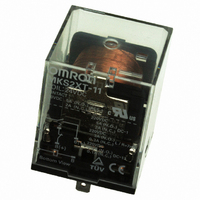
MKS2XTI-11 DC24
Manufacturer Part Number
MKS2XTI-11 DC24
Description
RELAY PWR DC DPST-OC 5A 24VDC
Manufacturer
Omron
Series
MK-S(X)r
Datasheet
1.MKS1XT-10_DC24.pdf
(12 pages)
Specifications of MKS2XTI-11 DC24
Relay Type
General Purpose
Coil Resistance
380 Ohms
Coil Type
Standard
Contact Form
DPST-NO/NC (1 Form A and B)
Contact Rating (current)
5A
Switching Voltage
220VDC - Max
Coil Current
63.2mA
Coil Voltage
24VDC
Turn On Voltage (max)
19.2 VDC
Turn Off Voltage (min)
3.6 VDC
Mounting Type
Socket
Termination Style
Socketable
Circuit
DPST-NO/NC (1 Form A and B)
Contact Rating @ Voltage
5A @ 220VDC
Control On Voltage (max)
19.2 VDC
Control Off Voltage (min)
3.6 VDC
Contact Rating
5 A
Contact Termination
Solder Lug
Mounting Style
PCB or DIN Rail
Power Consumption
1.5 W
Contact Material
Silver Tin Indium
Coil Voltage Vdc Nom
24V
Contact Current Max
5A
Contact Voltage Dc Nom
220V
Contact Configuration
SPST-NO / SPST-NC
Lead Free Status / RoHS Status
Lead free / RoHS Compliant
Lead Free Status / RoHS Status
Lead free / RoHS Compliant, Lead free / RoHS Compliant
Other names
MKS2XTI11DC24
Z2971
Z2971


Safety Precautions
Be sure to read the precautions and information common to all electromechanical relays, contained in the Technical User’s Guide,
“Electromechanical Relays, Technical Information” for correct use.
Precautions for Correct Use
Installation
• Models for DC loads (i.e., models with “X” in the model number)
• Models for AC loads do not contain a permanent magnet.
• When mounting a P7MF-06(-D) Front-mounting Socket to a DIN
Gang Mounting
Conditions for mounting multiple MKS-X relays on the same DIN rail.
* Gang mounting of the Front-Mounting Sockets is not possible if the
Wiring
• The contact terminals on Models for DC Loads (i.e., models with “X” in
• Be sure to check plarity when wiring DC coil MKS-X relays with
Models for
DC Loads
Models for
AC Loads
contact carry current exceeds 10A.Provide space on both the right
and left sides of the Sockets.
The mounting pitch is given in the following diagram.
have permanent magnets built into the insulating block. If a
permanent magnet or other magnetic body comes near the Relay,
magnetic interference will occur with the built-in permanent magnet
and the contact switching capacity will be decreased.
Track, attach PFP-M End Plates on both sides of the Socket to
prevent it from moving.
the model number) have polarity. Wiring with incorrect polarity may
result in inability to turn OFF the Relay or loss of functionality.
built-in operation indicators.
Relay
20
15
10
5
0
0
10
10A
15A
Rated current
of Relay
20
Mounting interval (mm)
30
Mounting interval
Back-Connecting
40
Socket
❍
❍
50
Socket
Front-Connecting
Socket
❍
*
General Purpose Power Relays
Operating Environment
Do not use the Relay in environments with combustible gas. Doing so
may result in explosion due to arcing.
Storage
Models for DC Loads (i.e., models with “X” in the model number) are
magnetized because they have a built-in magnet to deflect and
extinguish the arc. Do not install the Relay near IC cards or other
items that may be adversely affected by magnetism.
Usage
Use the Relay mounted in the P7M-06P or P7MF-06(-D) Socket.
Test Button
• Turn OFF the power supply before operating the test button. Always
• Do not use the test button as a switch.
• The durability of the test button is 100 operations minimum.
The circuit can be checked using either of two modes.
Test Button Applications
Example: Checking operation of Relays and sequence circuits.
return the test button to the original position after you use it.
(No tool is required.)
Press the button
Test Button
DC specification: Blue
AC specification: Red
for operation.
(momentary)
Mode 1
MKS-X
pressing down on the
Lock the contacts by
button and turning it.
(locked)
Mode 2
Normal
9
Related parts for MKS2XTI-11 DC24
Image
Part Number
Description
Manufacturer
Datasheet
Request
R

Part Number:
Description:
RELAY PWR DC DPST-OC 5A 120VAC
Manufacturer:
Omron
Datasheet:

Part Number:
Description:
MKS DC Square Base
Manufacturer:
Omron
Datasheet:
Part Number:
Description:
MKS DC Square Base
Manufacturer:
Omron
Datasheet:
Part Number:
Description:
MKS DC Square Base
Manufacturer:
Omron
Datasheet:
Part Number:
Description:
MKS DC Square Base
Manufacturer:
Omron
Datasheet:
Part Number:
Description:
RELAY PWR DC DPST-OC 5A 120VAC
Manufacturer:
Omron
Datasheet:
Part Number:
Description:
RELAY PWR DC DPST-OC 5A 24VDC
Manufacturer:
Omron
Datasheet:
Part Number:
Description:
MKS DC Square Base
Manufacturer:
Omron
Datasheet:
Part Number:
Description:
MKS DC Square Base
Manufacturer:
Omron
Datasheet:
Part Number:
Description:
MKS DC Square Base
Manufacturer:
Omron
Datasheet:
Part Number:
Description:
MKS DC Square Base
Manufacturer:
Omron
Datasheet:
Part Number:
Description:
MKS DC Square Base
Manufacturer:
Omron
Datasheet:
Part Number:
Description:
MKS DC Square Base
Manufacturer:
Omron
Datasheet:
Part Number:
Description:
MKS DC Square Base
Manufacturer:
Omron
Datasheet:

Part Number:
Description:
G6S-2GLow Signal Relay
Manufacturer:
Omron Corporation
Datasheet: