G9EC-1-B DC24 Omron, G9EC-1-B DC24 Datasheet - Page 4
G9EC-1-B DC24
Manufacturer Part Number
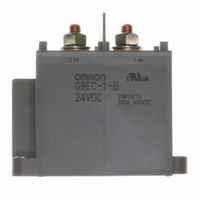
G9EC-1-B DC24
Description
RELAY IND SPST 200ADC WIRE TERM
Manufacturer
Omron
Series
G9EC-1r
Specifications of G9EC-1-B DC24
Relay Type
General Purpose
Coil Type
Standard
Contact Form
SPST-NO (1 Form A)
Contact Rating (current)
200A
Switching Voltage
400VDC - Max
Coil Current
469mA
Coil Voltage
24VDC
Turn On Voltage (max)
18 VDC
Turn Off Voltage (min)
1.92 VDC
Mounting Type
Chassis Mount
Termination Style
Screw Terminal
Circuit
SPST-NO (1 Form A)
Contact Rating @ Voltage
200A @ 400VDC
Control On Voltage (max)
18 VDC
Control Off Voltage (min)
1.92 VDC
Coil Voltage Vdc Nom
24V
Contact Current Max
200A
Contact Voltage Dc Nom
400V
Coil Resistance
51.2ohm
Contact Configuration
SPST-NO
Current, Rating
200 A
Dielectric Rating
2500 VAC
Dimensions
2.87 " L x 1.42 " W x 2.64 " H
Function
High Voltage
Material, Contact
Ag Alloy
Resistance, Coil
51.2 Ohms
Resistance, Contact
30 Milliohms (Max.)
Standards
UL, CSA
Temperature, Operating, Maximum
50 °C
Temperature, Operating, Minimum
-40 °C
Termination
Screw
Voltage, Control
24 VDC
Voltage, Drop, On-state
0.1 V (Max.)
Voltage, Rating
400 V
Lead Free Status / RoHS Status
Lead free / RoHS Compliant
Lead Free Status / RoHS Status
Lead free / RoHS Compliant, Lead free / RoHS Compliant
Other names
G9EC-1-B-DC24
G9EC-1-B-DC24
G9EC1B DC24
G9EC1BDC24
Z1619
G9EC-1-B-DC24
G9EC1B DC24
G9EC1BDC24
Z1619


4
1.4
1.2
0.8
0.6
0.4
0.2
1
0
The value at which malfunction occurred was
measured after applying shock to the test piece
3 times each in 6 directions along 3 axes.
Vibration Malfunction
1
Sample: G9EC-1
Number: 5
X
Z'
Shock Malfunction
Unit: m/s
Sample: G9EC-1
Number: 5
Deenergized
Confirmed area
5
DC Power Relays (200-A Models)
2
10
Y
Y'
800
600
400
200
200
400
600
800
1,000
1,000
50
Unconfirmed area
100
Y'
Energized
Frequency (Hz)
Y
X'
Z
X'
500
X
Z'
Z
1,000
−1.0
−2.0
−3.0
−4.0
−5.0
−1.0
−2.0
−3.0
−4.0
−5.0
Characteristics were measured after applying vibration
at a frequency of 10 to 55 Hz (single amplitude of 0.75
mm) to the test piece (not energized) for 2 hours each
in 3 directions. The percentage rate of change is the
average value for all of the samples
5.0
4.0
3.0
2.0
1.0
0.0
5.0
4.0
3.0
2.0
1.0
0.0
Characteristics were measured
of 490 m
along 3 axes
average value for all of the samples.
Shock Resistance
Vibration Resistance
Start
Start
Sample: G9EC-1
Number: 5
Sample: G9EC-1
Number: 5
2
/s to the test piece 3 times each in 6 directions
. The percentage rate of change is the
G9EC-1
Must-operate voltage
Must-release voltage
Must-release voltage
Must-operate voltage
after applying a shock
After test
After test
Related parts for G9EC-1-B DC24
Image
Part Number
Description
Manufacturer
Datasheet
Request
R

Part Number:
Description:
RELAY IND SPST 200ADC WIRE TERM
Manufacturer:
Omron
Datasheet:

Part Number:
Description:
RELAY DC IND SPST-NO 100VDC
Manufacturer:
Omron
Datasheet:
Part Number:
Description:
DC Power Relay
Manufacturer:
Omron
Datasheet:
Part Number:
Description:
DC Power Relay
Manufacturer:
Omron
Datasheet:

Part Number:
Description:
RELAY IND SPST 200ADC LEAD TERM
Manufacturer:
Omron
Datasheet:
Part Number:
Description:
RELAY SPST 200ADC LEAD TERM
Manufacturer:
Omron
Datasheet:
Part Number:
Description:
DC Power Relay
Manufacturer:
Omron
Datasheet:
Part Number:
Description:
DC Power Relay
Manufacturer:
Omron
Datasheet:
Part Number:
Description:
DC Power Relay
Manufacturer:
Omron
Datasheet:

Part Number:
Description:
Terminal Cover For G9EC
Manufacturer:
Omron
Datasheet:

Part Number:
Description:
RELAY, SPNO, 200A, 12VDC
Manufacturer:
Omron
Datasheet:
Part Number:
Description:
RELAY, SPNO, 200A, 24VDC
Manufacturer:
Omron
Datasheet:

Part Number:
Description:
G6S-2GLow Signal Relay
Manufacturer:
Omron Corporation
Datasheet:
Part Number:
Description:
Compact, Low-cost, SSR Switching 5 to 20 A
Manufacturer:
Omron Corporation
Datasheet: