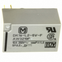
DK1A-L2-5V-F Panasonic Electric Works, DK1A-L2-5V-F Datasheet - Page 3

DK1A-L2-5V-F
Manufacturer Part Number
DK1A-L2-5V-F
Description
RELAY PWR SPST-NO 10A 5VDC PCB
Manufacturer
Panasonic Electric Works
Series
DKr
Specifications of DK1A-L2-5V-F
Relay Type
General Purpose
Contact Form
SPST-NO (1 Form A)
Contact Rating (current)
10A
Switching Voltage
250VAC
Coil Type
Latching, Dual Coil
Coil Current
40mA
Coil Voltage
5VDC
Turn On Voltage (max)
3.5 VDC
Mounting Type
Through Hole
Termination Style
PC Pin
Circuit
SPST-NO (1 Form A)
Contact Rating @ Voltage
10A @ 250VAC
Control On Voltage (max)
3.5 VDC
Brand/series
DK Series
Current, Rating
10 A
Function
Power
Number Of Pins
5
Power, Rating
2500⁄300 VA⁄W
Standards
UL, CSA, VDE, TUV
Termination
Solder
Voltage, Control
5 VDC
Voltage, Rating
380 VAC
Lead Free Status / RoHS Status
Lead free / RoHS Compliant
Control Off Voltage (min)
-
Lead Free Status / Rohs Status
RoHS Compliant part
Other names
255-2054
Available stocks
Company
Part Number
Manufacturer
Quantity
Price
Company:
Part Number:
DK1A-L2-5V-F
Manufacturer:
IR
Quantity:
1 400
DK
4. Coil temperature rise
Sample: DK1a1b-12V, 5 pcs.
Ambient temperature: 20 C 68 F
DIMENSIONS
1. 1 Form A type
2. 1 Form A 1 Form B type, 2 Form A type
50
40
30
20
10
0
80
90
Note:
Relay out-line and PC board pattern are common for both
1 Form A 1 Form B type and 2 Form A type.
100 110 120 130
Coil applied voltage,%V
.012
0.3
2.54
.100
.382
.016
.382
.012
9.7
.016
0.4
9.7
0.3
0.4
.012
.012
0.3
0.3
.382
.382
10.16
9.7
9.7
.400
0.6
.024
General tolerance: 0.3
7.62
.300
.031
2.54
.100
.016
.016
0.4
0.4
0.8
.787
.787
8 A
5 A
0 A
20
20
Single side stable type
2 coil latching type
0.8
.031
7.62
.300
7.62
.300
General tolerance: 0.3
10.16
.400
.016
0.4
7.62
.300
Single side stable type
.787
.787
20
20
0.8
.031
2 coil latching type
0.8
.031
1.11
.044
1.11
.044
7.62
.300
7.62
.300
0.8
.031
0.8
.031
.138
.138
3.5
3.5
5. Ambient temperature characteristics
2.42
.095
2.42
.095
0.8
.031
0.8
.031
1.11
.044
1.11
.044
.012
.138
.138
3.5
3.5
10.16
10.16
.400
.400
.591
.591
.047
.047
15
1.2
1.2
15
–40
.012
–20
0.4
.016
0.4
.016
10.16
10.16
12.5
.492
.400
12.5
.492
.400
PC board pattern (Copper-side view)
0
130
120
110
100
10.16
10.16
90
80
70
.400
.400
2.54
.100
0.4
.016
0.4
.016
20
Tolerance: 0.1
40
Pick-up
voltage
Drop-out
voltage
The above shows 2 coil latching type.
No.5 terminal is eliminated on single side
stable type.
10.16
60
PC board pattern (Copper-side view)
.400
10.16
10.16
.400
.400
7.62
.300
Ambient
temperature, C
80
2.54
.100
2.54
.100
Tolerance: 0.1
7.62
.300
7.62
.300
.004
7.62
.300
7.62
.300
.043 dia.
.043 dia.
1.1 dia.
1.1 dia.
7.62
.300
7.62
.300
.004
(Deenergized condition)
(Deenergized condition)
Since this is a polarized relay, the connection
to the coil should be done according to the
above schematic.
-
-
+
+
1
8
1
8
Single side stable
Single side stable
.043 dia.
.043 dia.
1.1 dia.
1.1 dia.
<1 Form A 1 Form B type>
Schematic (Bottom view)
3
6
3
6
Since this is a polarized relay,
the connection to the coil
should be done according to
the above schematic.
<2 Form A>
(Deenergized condition)
4
5
4
5
Single side stable
(Reset condition)
-
-
+
+
1
6
1
6
(Bottom view)
2 coil latching
Schematic
-
-
+
+
1
8
1
8
+
5
(Reset condition)
(Reset condition)
2 coil latching
2 coil latching
+
+
7
7
3
3
mm
6
6
3
3
4
4
inch
4
5
4
5


