DEMO908AP64 Freescale Semiconductor, DEMO908AP64 Datasheet - Page 9
DEMO908AP64
Manufacturer Part Number
DEMO908AP64
Description
BOARD DEMO FOR 908AP64
Manufacturer
Freescale Semiconductor
Type
Microcontrollerr
Datasheet
1.DEMO908AP64E.pdf
(16 pages)
Specifications of DEMO908AP64
Contents
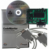
Board, CDs, Cable, Filter
Processor To Be Evaluated
MC68HC908AP
Data Bus Width
16 bit
Interface Type
RS-232
Silicon Manufacturer
Freescale
Core Architecture
HC08
Core Sub-architecture
HC08
Silicon Core Number
MC68HC908
Silicon Family Name
HC08AP
Kit Contents
Demo Board, Cables, Software, Guides
Rohs Compliant
No
For Use With/related Products
MC68HC908AP Family
Lead Free Status / RoHS Status
Contains lead / RoHS non-compliant


D E M O 9 0 8 A P 6 4
PWR_SEL Jumper
The PWR_SEL jumper selects the source of power input to the module, or allows regulated
+3.3VDC to be provided to J1 for use by external circuits. The module takes voltage input
from the 2-position on-board voltage regulator or from the 40-pin MCU connector (J1). Power
input at the terminal block must be DC voltage between +5VDC and +16VDC. Power input on
the MCU connector must be regulated voltage between +3.0VDC and +3.3VDC.
MCU_PORT connector power input allows use of batteries, or other alternate sources, to
power the module.
The PWR_SEL option jumper provides 3 possible configurations; source power from the PWR
connector, source power from J1, or source power from PWR and supply power to J1. The
figures below show the settings for each configuration.
Figure 2: PWR_SEL Jumper Settings
Reset Switch
The RESET switch provides a method to apply an asynchronous reset to the module. Press-
ing the RESET switch applies a low voltage level to the RST* input. A resistor tied to the high
voltage rail prevents spurious RESET input to the MCU. A capacitor tied to ground holds the
signal line low for a sufficient amount of time.
NOTE: Power output from the module is limited by the 250 mA maximum output
CAUTION: Module damage may occur if the MCU_PORT power input pin (J1-1)
NOTE: Power output from the module is limited by the 250 mA maximum out-
1
2
1
2
1
2
of the on-board voltage regulator.
• •
• •
• •
• •
• •
• •
put of the on-board voltage regulator.
is over-driven.
Module powered from external +3.0VDC - +3.3VDC input con-
nected to J1-1 (+) and J1-3 (-)
Module powered from external +5VDC - +16VDC connected to
TB1 Terminal Block. J1-1 is open or not connected.
Module powered from external +5VDC - +16VDC connected to
TB1 Terminal Block. Module provides +3.3VDC output (up to 50
mA) at pin J1 for use by external circuits.
9
J U N E
2 8 ,
2 0 0 4
The
Related parts for DEMO908AP64
Image
Part Number
Description
Manufacturer
Datasheet
Request
R

Part Number:
Description:
Manufacturer:
STMicroelectronics
Datasheet:

Part Number:
Description:
DEMO BOARD FOR HMC6042/HMC1041Z
Manufacturer:
Honeywell Microelectronics & Precision Sensors

Part Number:
Description:
DEMO BOARD FOR HMC1042L/HMC1041Z
Manufacturer:
Honeywell Microelectronics & Precision Sensors
Datasheet:

Part Number:
Description:
KIT DEMO 4 SENSOR CHAN RS232
Manufacturer:
VTI Technologies
Datasheet:


Part Number:
Description:
DEMO: DC Power Supply, 32 Volts, 3 Amps
Manufacturer:
Tektronix
Part Number:
Description:
DEMO: Programmable DC Power Supply, 32 Volts, 3 Amps
Manufacturer:
Tektronix

Part Number:
Description:
Manufacturer:
Freescale Semiconductor, Inc
Datasheet:
Part Number:
Description:
Manufacturer:
Freescale Semiconductor, Inc
Datasheet:
Part Number:
Description:
Manufacturer:
Freescale Semiconductor, Inc
Datasheet:
Part Number:
Description:
Manufacturer:
Freescale Semiconductor, Inc
Datasheet:
Part Number:
Description:
Manufacturer:
Freescale Semiconductor, Inc
Datasheet:
Part Number:
Description:
Manufacturer:
Freescale Semiconductor, Inc
Datasheet:
Part Number:
Description:
Manufacturer:
Freescale Semiconductor, Inc
Datasheet:
Part Number:
Description:
Manufacturer:
Freescale Semiconductor, Inc
Datasheet: