CP2101EK Silicon Laboratories Inc, CP2101EK Datasheet - Page 7
CP2101EK
Manufacturer Part Number
CP2101EK
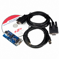
Description
KIT DEVELOPMENT RS232 TO USB
Manufacturer
Silicon Laboratories Inc
Specifications of CP2101EK
Processor To Be Evaluated
CP2101
Interface Type
RS-232, USB
Lead Free Status / RoHS Status
Contains lead / RoHS non-compliant
Lead Free Status / RoHS Status
Lead free / RoHS Compliant, Contains lead / RoHS non-compliant
Other names
336-1076
CP2101EK
Q1572300
CP2101EK
Q1572300


4.
SUSPEND
SUSPEND
*Note: Pins can be left unconnected when not used.
REGIN
Name
VBUS
GND
RXD
DSR
DCD
RST
TXD
CTS
RTS
DTR
V
NC
D+
D–
RI
DD
Pinout and Package Definitions
10, 13–22
Pin #
23*
24*
27*
28*
12*
11*
26
25
1*
2*
6
3
9
7
8
4
5
Power Out
Power In
Power In 5 V Regulator Input. This pin is the input to the on-chip voltage regula-
D Out
D Out
D Out
D Out
D Out
D I/O
D I/O
D I/O
Type
D In
D In
D In
D in
D In
D In
Table 4.1. Pin Definitions for the CP2101
3.0–3.6 V Power Supply Voltage Input.
3.3 V Voltage Regulator Output. See Section 9.
Ground
Device Reset. Open-drain output of internal POR or V
external source can initiate a system reset by driving this pin low for at
least 15 µs.
tor.
VBUS Sense Input. This pin should be connected to the VBUS signal
of a USB network. A 5 V signal on this pin indicates a USB network
connection.
USB D+
USB D–
Asynchronous data output (UART Transmit)
Asynchronous data input (UART Receive)
Clear To Send control input (active low)
Ready to Send control output (active low)
Data Set Ready control input (active low)
Data Terminal Ready control output (active low)
Data Carrier Detect control input (active low)
Ring Indicator control input (active low)
This pin is driven high when the CP2101 enters the USB suspend
state.
This pin is driven low when the CP2101 enters the USB suspend state.
These pins should be left unconnected or tied to V
Rev. 1.8
Description
DD
.
DD
CP2101
monitor. An
7
Related parts for CP2101EK
Image
Part Number
Description
Manufacturer
Datasheet
Request
R

Part Number:
Description:
IC CTRLR BRIDGE USB-UART 28MLP
Manufacturer:
Silicon Laboratories Inc
Datasheet:

Part Number:
Description:
IC CTRLR BRIDGE USB-UART 28MLP
Manufacturer:
Silicon Laboratories Inc
Datasheet:
Part Number:
Description:
IC USB-TO-UART BRIDGE 28MLP
Manufacturer:
Silicon Laboratories Inc
Datasheet:
Part Number:
Description:
SMD/C°/SINGLE-ENDED OUTPUT SILICON OSCILLATOR
Manufacturer:
Silicon Laboratories Inc
Part Number:
Description:
Manufacturer:
Silicon Laboratories Inc
Datasheet:
Part Number:
Description:
N/A N/A/SI4010 AES KEYFOB DEMO WITH LCD RX
Manufacturer:
Silicon Laboratories Inc
Datasheet:
Part Number:
Description:
N/A N/A/SI4010 SIMPLIFIED KEY FOB DEMO WITH LED RX
Manufacturer:
Silicon Laboratories Inc
Datasheet:
Part Number:
Description:
N/A/-40 TO 85 OC/EZLINK MODULE; F930/4432 HIGH BAND (REV E/B1)
Manufacturer:
Silicon Laboratories Inc
Part Number:
Description:
EZLink Module; F930/4432 Low Band (rev e/B1)
Manufacturer:
Silicon Laboratories Inc
Part Number:
Description:
I°/4460 10 DBM RADIO TEST CARD 434 MHZ
Manufacturer:
Silicon Laboratories Inc
Part Number:
Description:
I°/4461 14 DBM RADIO TEST CARD 868 MHZ
Manufacturer:
Silicon Laboratories Inc
Part Number:
Description:
I°/4463 20 DBM RFSWITCH RADIO TEST CARD 460 MHZ
Manufacturer:
Silicon Laboratories Inc
Part Number:
Description:
I°/4463 20 DBM RADIO TEST CARD 868 MHZ
Manufacturer:
Silicon Laboratories Inc
Part Number:
Description:
I°/4463 27 DBM RADIO TEST CARD 868 MHZ
Manufacturer:
Silicon Laboratories Inc