28031 Parallax Inc, 28031 Datasheet - Page 6
28031
Manufacturer Part Number
28031
Description
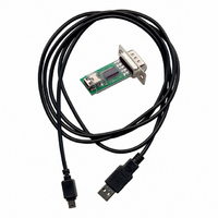
ADAPTER USB TO SRL RS232 W/CABLE
Manufacturer
Parallax Inc
Datasheet
1.28138.pdf
(10 pages)
Specifications of 28031
Accessory Type
USB to RS232 Adapter
Product
Microcontroller Accessories
Lead Free Status / RoHS Status
Lead free / RoHS Compliant
For Use With/related Products
Parallax Motherboards
For Use With
28136 - KIT SCRIBBLER ROBOT28138 - BOARD DEV PROFESSIONAL
Lead Free Status / Rohs Status
Lead free / RoHS Compliant
Available stocks
Company
Part Number
Manufacturer
Quantity
Price


BS2p40 Pin Connections
Due to the physical pin configuration of the BS2p40, connections to the MAINIO (M) and AUXIO (A) pins
are distributed between the BASIC Stamp and SX28AC/DP connectors. Use the tables below when using
the BS2p40 on the PDB.
Circuit Diagrams
The sections that follow describe the various circuits on the PDB, and provide hints and guidance for their
use.
Discrete LEDs (X17)
The PDB is equipped with 16 discrete LEDs, wired in an active-high configuration as shown at right. To
illuminate an LED, drive its control pin (on X17) high.
7-Segment LED Displays (X19 and X18)
The PDB is equipped with five common-cathode, 7-segment LED displays. To illuminate a segment, that
segment (on X18) is driven high and the associated digit control line (on X19) is driven low (or connected
to Vss). Note that the displays are designed to be multiplexed (the segment lines are shared), hence a
suitable multiplexer like the MAX7219 or MC14489 should be used for BASIC Stamp or Javelin Stamp
applications. For simple, single-digit displays the digit control line may be connected directly to Vss.
Parallel LCD Connector (X2)
Box header X1 provides the connection for an HD44780-compatible LCD module.
Connection to the circuit is made via X2. Note that X2 is configured such that the
LCD data buss (DB0 – DB7) is split, and the E, RW, and RS lines have dual
connections as shown in the diagram at right.
This configuration allows both 4- and 8-bit LCD applications to be developed. The
potentiometer located near X1 is used to adjust LCD display contrast.
Copyright © Parallax, Inc.
RC0
RB0
M0
M8
P0
A0
A8
P8
RC1
RB1
M1
M9
P1
A1
A9
P9
Professional Development Board (#28138)
RC2
M10
RB2
A10
P10
M2
P2
A2
RC3
M11
RB3
A11
P11
M3
P3
A3
RC4
M12
RB4
A12
P12
M4
P4
A4
M13
RB5
RC5
A13
P13
M5
P5
A5
M14
RB6
RC6
A14
P14
M6
P6
A6
M15
RB7
RC7
A15
P15
M7
P7
A7
v2.0 9/3/2008 Page 6 of 10
Related parts for 28031
Image
Part Number
Description
Manufacturer
Datasheet
Request
R


Part Number:
Description:
Microcontroller Modules & Accessories DISCONTINUED BY PARALLAX
Manufacturer:
Parallax Inc

Part Number:
Description:
BOOK UNDERSTANDING SIGNALS
Manufacturer:
Parallax Inc
Datasheet:


Part Number:
Description:
COMPETITION RING FOR SUMOBOT
Manufacturer:
Parallax Inc
Datasheet:


Part Number:
Description:
TEXT INFRARED REMOTE FOR BOE-BOT
Manufacturer:
Parallax Inc
Datasheet:
Part Number:
Description:
BOARD EXPERIMENT+LCD NX-1000
Manufacturer:
Parallax Inc
Datasheet:

Part Number:
Description:
CONTROLLER 16SERVO MOTOR CONTROL
Manufacturer:
Parallax Inc
Datasheet:

Part Number:
Description:
BASIC STAMP LOGIC ANALYZER
Manufacturer:
Parallax Inc
Datasheet:

Part Number:
Description:
IC MCU 2K FLASH 50MHZ SO-18
Manufacturer:
Parallax Inc
Datasheet: