Z8ENCORE000ZAC Zilog, Z8ENCORE000ZAC Datasheet - Page 3
Z8ENCORE000ZAC
Manufacturer Part Number
Z8ENCORE000ZAC
Description
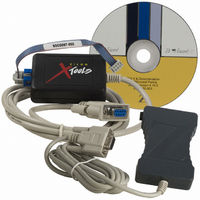
KIT Z8 ENCORE SMART CABLE ACCESS
Manufacturer
Zilog
Datasheet
1.Z8ENCORE000ZAC.pdf
(6 pages)
Specifications of Z8ENCORE000ZAC
Accessory Type
Serial Smart Cable
Interface Type
RS-232
For Use With/related Products
Z8 Encore! Dev. Kits
Lead Free Status / RoHS Status
Contains lead / RoHS non-compliant
Other names
269-3248


Consider the following points when connecting the Smart Cable to your development
board:
•
•
•
•
Follow the steps below to provide the crystal frequency:
1. Select Settings from the Project menu.
UM016207-0508
Vertical
Groove
Horizontal
Groove
Note:
Note:
The DBG interface connector requires the V
Z8 Encore! on your design/application board.
The minimum signal connections required to connect the Z8 Encore! to the Smart
Cable are the AV
The AV
externally connected to the V
The Z8 Encore! must be clocked to generate the DBG timing signals. For the
recommended crystal oscillator circuit, refer to Product Specification of target MCU.
Caution:
The Smart Cable receives power from the target design/application board.
You must enter the crystal frequency running the Z8 Encore! device when cre-
ating a new project in ZDS II.
DD
Figure 3. DBG Interface Connector Pin 1 Location
must be externally connected to the V
The power to your design/application board must be turned OFF when
connecting or disconnecting the Smart Cable.
DD
, V
DD
, AV
SS
SS
.
, V
SS
, and the DBG pin signals.
DD
, V
SS
Pin 1
, and the DBG signals from the
DD
Pin 2
. The AV
Z8 Encore!
Pin 3
Pin 4
Z8ENCORE000ZAC
SS
Pin 5
®
must also be
Smart Cable
Pin 6
Page 3 of 6
Related parts for Z8ENCORE000ZAC
Image
Part Number
Description
Manufacturer
Datasheet
Request
R

Part Number:
Description:
Communication Controllers, ZILOG INTELLIGENT PERIPHERAL CONTROLLER (ZIP)
Manufacturer:
Zilog, Inc.
Datasheet:

Part Number:
Description:
KIT DEV FOR Z8 ENCORE 16K TO 64K
Manufacturer:
Zilog
Datasheet:

Part Number:
Description:
KIT DEV Z8 ENCORE XP 28-PIN
Manufacturer:
Zilog
Datasheet:

Part Number:
Description:
DEV KIT FOR Z8 ENCORE 8K/4K
Manufacturer:
Zilog
Datasheet:

Part Number:
Description:
KIT DEV Z8 ENCORE XP 28-PIN
Manufacturer:
Zilog
Datasheet:

Part Number:
Description:
DEV KIT FOR Z8 ENCORE 4K TO 8K
Manufacturer:
Zilog
Datasheet:
Part Number:
Description:
CMOS Z8 microcontroller. ROM 16 Kbytes, RAM 256 bytes, speed 16 MHz, 32 lines I/O, 3.0V to 5.5V
Manufacturer:
Zilog, Inc.
Datasheet:
Part Number:
Description:
Low-cost microcontroller. 512 bytes ROM, 61 bytes RAM, 8 MHz
Manufacturer:
Zilog, Inc.
Datasheet:
Part Number:
Description:
Z8 4K OTP Microcontroller
Manufacturer:
Zilog, Inc.
Datasheet:
Part Number:
Description:
CMOS SUPER8 ROMLESS MCU
Manufacturer:
Zilog, Inc.
Datasheet:
Part Number:
Description:
SL1866 CMOSZ8 OTP Microcontroller
Manufacturer:
Zilog, Inc.
Datasheet:
Part Number:
Description:
SL1866 CMOSZ8 OTP Microcontroller
Manufacturer:
Zilog, Inc.
Datasheet:
Part Number:
Description:
OTP (KB) = 1, RAM = 125, Speed = 12, I/O = 14, 8-bit Timers = 2, Comm Interfaces Other Features = Por, LV Protect, Voltage = 4.5-5.5V
Manufacturer:
Zilog, Inc.
Datasheet:
Part Number:
Description:
Manufacturer:
Zilog, Inc.
Datasheet: