FS2003(US) Equinox Technologies, FS2003(US) Datasheet
FS2003(US)
Specifications of FS2003(US)


Related parts for FS2003(US)


FS2003(US) Summary of contents
Page 1
...
Page 2
Contents Copyright Information .............................................................................................................1 Equinox Warranty Information ...............................................................................................2 Electromagnetic Compatibility (EMC) Compliance..............................................................4 Technical Support....................................................................................................................5 Product Documentation ..........................................................................................................6 1.0 Programmer Overview / Specifications.........................................................................10 1.1 System Contents ..........................................................................................................10 1.2 Hardware Overview (external layout) ...........................................................................11 1.3 Hardware Overview (internal layout) ............................................................................12 1.4 Programmer ...
Page 3
Programmer – Getting Started Guide ............................................................................36 3.1 Software Overview ........................................................................................................36 3.2 Programmer Control Mechanisms ................................................................................37 3.3 Software Installation......................................................................................................38 3.4 Programmer Operating Modes .....................................................................................39 3.5 Development Mode (EDS) ............................................................................................41 3.5.1 Overview...............................................................................................................41 3.5.2 Creating a new EDS (Development Mode) Project..............................................41 3.5.3 ...
Page 4
... Copyright Equinox Technologies UK Limited. All rights reserved Atmel ...
Page 5
... Equinox Warranty Information This product is guaranteed by Equinox Technologies (UK) Limited for a period of 12 months (1 year) after the date of purchase against defects due to faulty workmanship or materials. One guarantee covers both parts and labour. Service under the guarantee is only provided upon presentation of reasonable evidence that the date of the claim is within the guarantee period (e.g. completed registration/guarantee card or a purchase receipt) ...
Page 6
... Equinox Technologies UK Ltd. cannot be held responsible for any programming problems which are ‘out of our control’. This type of problem is usually listed in the ‘Errata Sheet’ for the particular device being programmed and is available from the silicon vendor. Information contained in this manual is for guidance purposes only and is subject to change. E& ...
Page 7
Electromagnetic Compatibility (EMC) Compliance The ‘FS2003 Programmer’ Approved Product designed for use in an ESD controlled environment i.e. development or production. This means, therefore, that the user must ensure that there is no possibility of ...
Page 8
Technical Support It is often the case that users experience problems when installing or using a product for the first time. If you have a technical support problem, please consult the following list for help: Manual On-line help Press <F1> ...
Page 9
Product Documentation This manual provides an overview of the contents of the FS2003 Programming System plus associated hardware and software. References may be made to other hardware and software products which are not covered in detail in this manual. Please ...
Page 10
Configit – Firmware Upgrade Utility This utility is used to upgrade the firmware of the programmer if the firmware version is < 3.00. A firmware update may be required to add support for new devices and to correct any firmware ...
Page 11
Downloading up-to-date documentation and software: In line with our policy of continuous improvement, the software and associated documentation for this product are updated on a regular basis. Please refer to the ‘Downloads Page’ for this product on our website at ...
Page 12
FS2003 ISP Programmer - User Guide V1.08 – August 08 9 ...
Page 13
Programmer Overview / Specifications 1.1 System Contents The FS2003 programmer comes compete with an external mains power supply, PC Driver Software and cables. Please see the full contents list detailed below. 10 Hardware • FS2003 ISP Programmer • External ...
Page 14
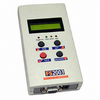
Hardware Overview (external layout) FS2003 ISP Programmer - User Guide V1.08 – 1 Top Panel ISP Cable Slot ISP cable plugs into relevant ISP Header internally and then exits the case through this slot. Front Panel <Target Vcc> LED ...
Page 15
Hardware Overview (internal layout) 12 Hardware 1. Atmel 6-way ISP (SPI) Header (J3) 2. Equinox 10-way ISP (SPI / UART) Header (J6) 3. Atmel 10-way ISP (SPI) Header (J7) 4. Jumper (J9) – Vcc Link 5. Liquid Crystal Display ...
Page 16
Programmer Specifications Overview The table below details the hardware specifications for the programmer. Please refer to the stated section for further information about any specific parameter. # Parameter Description / comment 1 Target Device See Device Support List Support ...
Page 17
Voltage Detection • LED 10 PC Control Software The programmer can be controlled using: As standard: • • • Optional chargeable upgrades: • • • • 11 EQTools / ISP-PRO PC running Windows 2000 / ME ...
Page 18
Max current = 300 mA. 18 Target SPI The programmer supports three SPI speeds: • Frequency • • ( SPI speeds are estimations only due to uneven mark/space ratio and non-continuous waveforms) 19 Target JTAG The programmer supports a user-defined ...
Page 19
Temperature range deg Dimensions 189H x 80L x 31D mm 28 Shipped Weight 0. Connects to spare PC COM port All 9 connections must be made in serial cable. ...
Page 20
Device Support 1.5.1 Devices supported by the programmer The programmer supports the following devices (at the time of this manual going to press): # Silicon Family vendor 1 Atmel AT89S 2 Atmel AT90S (AVR) 3 Atmel AT90CAN 4 Atmel ...
Page 21
Key: S – Device supported as standard U – Chargeable license upgrade required * – Support to be announced – please contact Equinox for a Support Date For an up-to-date Device Support list, please refer to the ‘Device Support’ section ...
Page 22
DC Power Input Connector (CON1 possible to power the programmer from an external power supply by plugging the DC Power Cable supplied with the programmer into CON1. This connector is a 2.5mm jack socket. Fig. 1.6.1 CON1 ...
Page 23
J5 – RS-232 Communications Port & Serial Cables 1.8.1 Connecting the programmer to the PC COM port The programmer communicates with a PC via the RS-232 Communications Port (J5). A suitable 9- way to 9-way serial cable is supplied ...
Page 24
Serial Cable Pin-outs Fig. 1.8.3.1 Pin-out RS-232 Communications Port Pin No. RS232 pin Description 1 DCD Not Connected 2 RXD Receive 3 TXD Transmit 4 DTR Not Connected 5 0 Volt 0V 6 DSR Not Connected ...
Page 25
Hardware Installation 2.1 Overview This section details how to set up the programmer hardware including Power Supply, Earthing Requirements, PC Serial Port Connection and ISP Header Selection. 2.2 ESD Precautions • • • • • 22 Work in a ...
Page 26
Removing the programmer cover a Remove programmer from all packaging and place display-side down on a flat surface b Remove all four screws from the back of the programmer (if fitted) c Remove programmer cover to reveal internal electronics ...
Page 27
Powering the Programmer / Target System 2.4.1 Select the required method of powering the Programmer / Target System The programmer supports the following power supply methods: Sect Power Supply method 2.4.2 Powering the Target System at +5.0V from the ...
Page 28
Fig. 2.4.1 FS2003 – Power Supply Overview Schematic FS2003 ISP Programmer - User Guide V1.08 – August 08 25 ...
Page 29
Powering the Target System at +5.0V from the programmer (external mains power supply adaptor) 2.4.3. Powering the Target System at +5.0V from the programmer (external bench power supply) 26 • Plug power supply jack into mating jack socket CON ...
Page 30
Powering the programmer from the Target System at 3.0 – 5.0V 2.4.5 Programmer and Target System are Independently powered FS2003 ISP Programmer - User Guide V1.08 – 1 • The Target System can supply power to the programmer as ...
Page 31
Selecting the correct ISP (In System Programming) Header a Select the required ISP Header and then plug the ISP Cable into this Header. Please refer to section 4 of this manual for full details of all the available headers. ...
Page 32
Connecting the programmer to the PC Serial (COM) Port The programmer communicates with a PC via the RS-232 Communications Port (J5). The programmer is supplied with the following PC Serial Cables / Adaptors: • 9-way D (Female) to 9-way ...
Page 33
Earthing requirements 2.7.1 Overview When setting up the programmer to In-System Program (ISP) a device on a Target System, extreme care must be taken to ensure that the 0V of the PC, programmer, Target System and any external devices ...
Page 34
Earthing recommendations To avoid catastrophic damage to PC, programmer or target system: • Ensure that both your target system and PC are connected to a common earth point • Make sure that all interconnections are made before applying power ...
Page 35
Testing the programmer hardware a Apply power to the programmer If you have a ‘Current Limit’ on your power supply, turn it to approximately 20mA and then gradually increase it until the programmer ‘FAIL’ LED starts to FLASH. b ...
Page 36
Re-assembling the programmer a Re-fit lid to programmer b Re-fit the four screws in the back of the case c Ensure that the PC, programmer and Target System power is switched OFF. Please note: • The FAIL LED will ...
Page 37
Hardware - Fault Finding Guide i. Target Vcc LED does not illuminate when power is applied to the Programmer / Target System ii. No Programming Projects Loaded NO / INVALID PROJECT LOADED! iii. FAIL LED constantly flashing 34 • ...
Page 38
FS2003 ISP Programmer - User Guide V1.08 – August 08 35 ...
Page 39
Programmer – Getting Started Guide 3.1 Software Overview The FS2003 programmer is supplied with a comprehensive Integrated Development Environment (IDE) called ‘EQTools Version 2.xx Software Suite’. This software supports creation and testing of so-called Programming Projects which can then ...
Page 40
Programmer Control Mechanisms The programmer can be controlled from EQTools, from a Remote System and via the Equinox ISP- PRO software. An overview of the various control mechanisms is given below. Standalone Operation (Keypad) This indicates that the programmer ...
Page 41
Software Installation The FS2003 programmer comes with the software suite called EQTools as standard. The latest version of this software which was available at the time of shipping is supplied on CD-ROM with the programmer. However, this software version ...
Page 42
Programmer Operating Modes The FS2003 programmer can be controlled in various different ways as detailed in the table below: # Programmer Connect Control Method Mode Software COM Port 1 Development Yes EQTools - EDS Mode 2 ...
Page 43
ASCII Control Yes ASCII Text Mode Communications Key S – feature available as standard U – a license upgrade must be purchased from Equinox to enable this feature. 40 Upgrade In this mode, the programmer Required is controlled via ...
Page 44
Development Mode (EDS) 3.5.1 Overview In ‘Development Mode’, the programmer is controlled from the EQTools – EDS (Equinox Development Suite) running on a PC. The Development utility is called Equinox Development Suite or EDS for short. In this mode ...
Page 45
At the end of the EDS Wizard: Click the <Test> button Save the EDS file with an appropriate name eg. ATmega163.eds The EDS Window will now launch – see section 2.5.4 3.5.3 Testing an existing Programming Project in a ...
Page 46
Overview of EDS – Development Mode The EDS Utility consists of a series of tabs. Each tab controls a different area of functionality including FLASH Area Programming, EEPROM Area programming, Configuration Fuse Programming and Security Fuse programming ...
Page 47
Fig.3.5.4.2 FLASH / EEPROM tab – functional description # 1 File name and This specifies the ‘File Name / path’ and ‘Last updated’ date of the file to be properties loaded into the Buffer Window. • • 2 Re-load file ...
Page 48
Buffer Window - Control Buttons The Buffer Window within EDS is used as a virtual data store which allows data to be transferred from file Buffer Window Target Device and vice-versa. The ‘Buffer – Control Buttons’ support operations on ...
Page 49
Example of using EDS Here is an example of how to use EDS: • Select the <FLASH> tab • Click the <Load> button to load a file • Click the <Check Sig> button to check the Device Signature of ...
Page 50
Standalone Keypad Mode 3.6.1 Overview In ‘Standalone Mode’, the FS2003 is controlled via the push buttons on the front panel of the programmer. The programmer LCD and the LED Status Indicators are used to display the current status of ...
Page 51
In Standalone Mode you can: • Select from Independent Programming Projects using the keypad and display • Plug the Programmer ISP cable into a Target System • Program the selected Programming Project into the Target ...
Page 52
Push Button Functions Button FS2003 ISP Programmer - User Guide V1.08 – 1 The FS2003 programmer features a four button keypad which is used to control the programmer when it is operating in ‘Standalone Mode’. The function of these ...
Page 53
Standalone Keypad Operation – step-by-step guide The instructions below detail how to operate the programmer in Standalone Mode using the programmer keypad and LCD not required while operating in Standalone Mode. 1. Ensure that you have ...
Page 54
Wait for the programmer to CRC check the Programming Project • The programmer performs a full CRC validation check of the entire Programming Project stored in the programmer ‘FLASH Memory Store’. • If the check is OK, the programmer ...
Page 55
Programming Project – FAIL If the Programming Project fails for some reason: • The <FAIL> LED will FLASH • The programmer will automatically remove power from the Target System (if the programmer is controlling power) • The LCD will ...
Page 56
Standalone Keypad Operation – Flowchart The flowchart below details how a ‘Programming Project’ is selected in ‘Standalone Mode’. Select Project Project1 T <UP> <DOWN> key key T Select Project Project2 T <UP> <DOWN> key key T Select Project Projectn ...
Page 57
Programmer Status LED’s The current status of the programmer is displayed on the programmer Status LED’s as detailed in the table below. Fig. 2.6.5 Programmer Status LED’s – state descriptions Status LED State Display WAITING BUSY FAIL PASS Status ...
Page 58
ASCII Text Communications Mode 3.7.1 Overview The ‘ASCII Text Control’ communications protocol or ‘ATC’ is designed as a simple way for a Remote Test System to control the basic programming operations of an Equinox programmer via an RS-232 serial ...
Page 59
Further Information A full description of this protocol can be found in the Application Note ‘AN110 - ASCII Text Control (ATC) Protocol for Remote Control of Equinox Programmers’. 56 FS2003 ISP Programmer - User Guide V1.08 – ...
Page 60
Script Mode ‘Script Mode’ is designed for production users who require logging of all programmer operations to a database. This mode utilises the Equinox ISP-PRO software which allows execution of Programming Scripts possible to write scripts to ...
Page 61
ISP Header Selection 4.1 Overview The FS2003 programmer caters for many different connection methods to a Target System by featuring FOUR possible ISP Header connectors. Each header provides the necessary signals to program the Target Device plus Vcc (power) ...
Page 62
ISP Header Selection Chart (by header) The FOUR ISP Headers featured on the FS2003 are detailed in the table below. Please refer to the section indicated in the ‘refer to section’ column for specific details of each header. # ...
Page 63
J8 Atmel 10-way JTAG Header Device support: Atmel ATmega32/128 + any new devices with JTAG port 60 4.9 FS2003 ISP Programmer - User Guide V1.08 – August 2008 ...
Page 64
ISP Header Selection Chart (by Device) The table below details which header to choose for a specified device or device family. The information contained in this manual does NOT show the actual connections to the Target Microcontroller. Please refer ...
Page 65
J3 - Atmel 6-way ISP Header (SPI Interface) This connection method is suitable for interfacing the programmer to a Target System which features the following: • Atmel 6-way IDC ISP Header • An Atmel device which features the 3-wire ...
Page 66
PROG_RESET O 6 PROG_GND P Key O - Output from programmer to Target Device I - Input to programmer from Target Device P - Passive eg. GROUND and power rails N/C - Not connected FS2003 ISP Programmer - User ...
Page 67
J6(a) - Equinox 10-way Header (Generic SPI Interface) This connection method is suitable for interfacing the programmer to a Target System which features the following: • Equinox 10-way IDC ISP Header • An Atmel device which features the 3-wire ...
Page 68
PROG_TSCK2 O 4 PROG_MOSI PROG_MISO I 7 PROG_GND P 8 PROG_SCK1 O 9 PROG_GND P 10 PROG_RESET O FS2003 ISP Programmer - User Guide V1.08 – 1 XTAL1 SCK2 Clock Output (*Optional*) This output ...
Page 69
Key O - Output from programmer to Target Device I - Input to programmer from Target Device P - Passive eg. GROUND and power rails N/C - Not connected 66 FS2003 ISP Programmer - User Guide V1.08 – ...
Page 70
J6(b) - Equinox 10-way Header (ATtiny11/12/15 HV Interface) This connection method is suitable for interfacing the programmer to a Target System which features the following: • Equinox 10-way IDC ISP Header • An Atmel ATtiny microcontroller eg. ATtiny11/12/15 • ...
Page 71
PROG_SDI PROG_SII O 7 PROG_GND P 8 PROG_SDO I 9 PROG_GND P 10 PROG_RESET/VPP O Key O - Output from programmer to Target Device I - Input to programmer from Target Device P - ...
Page 72
J6(c) - Equinox 10-way Header (UART Boot Loader) This connection method is suitable for interfacing the FS2003 programmer to a Target System which features the following: • Equinox 10-way IDC ISP Header • An Atmel Wireless T89C51Rx2 / CC01 ...
Page 73
N PROG_RXD I 7 PROG_GND P 8 PROG_ACTIVE O 9 PROG_GND P 10 PROG_RESET O Key O - Output from programmer to Target Device I - Input to programmer from Target Device P - Passive eg. GROUND ...
Page 74
J7 - Atmel 10-way Header (SPI Interface) This connection method is suitable for interfacing the programmer to a Target System which features the following: • Atmel 10-way IDC ISP Header • An Atmel device which features the 3-wire SPI ...
Page 75
PROG_RESET O 6 PROG_GND P 7 PROG_SCK1 O 8 PROG_GND P 9 PROG_MISO I 10 PROG_GND P Key O - Output from programmer to Target Device I - Input to programmer from Target Device P - Passive eg. GROUND ...
Page 76
J8 - Atmel 10-way JTAG Header (JTAG Interface) This connection method is suitable for interfacing the programmer to a Target System which features the following: • An Atmel device which features a JTAG ISP port e.g. ATmega128 / 323 ...
Page 77
PROG_VCC PROG_TDI O 10 PROG_GND P Key O - Output from programmer to Target Device I - Input to programmer from Target Device P - Passive eg. GROUND and power rails N/C - Not ...
Page 78
ISP Cable considerations The programmer is supplied with a single 10-way ISP Cable as standard. This cable is terminated with a 10-way IDC 0.1” female polarised plug at each end. The cable is wired as a so-called ‘straight- through’ ...