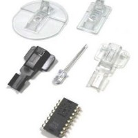
ADNK-3061 Avago Technologies US Inc., ADNK-3061 Datasheet - Page 6

ADNK-3061
Manufacturer Part Number
ADNK-3061
Description
KIT REFERENCE DESIGN ADNK-3060
Manufacturer
Avago Technologies US Inc.
Specifications of ADNK-3061
Main Purpose
Reference Design, Optical Mouse
Utilized Ic / Part
ADNS-3060, CY7C63743-PC
Description/function
Optical Mouse Sensor Kit
Interface Type
USB
Product
Display Modules
Touch Panel
No Touch Panel
For Use With/related Products
CY7C63743-PC
Lead Free Status / RoHS Status
Lead free / RoHS Compliant
Lead Free Status / RoHS Status
Lead free / RoHS Compliant, Lead free / RoHS Compliant
3. Enumeration
The host initiates SETUP transactions that reveal general
and device specific information about the mouse. When
the description is received, the host assigns a new and
unique USB address to the mouse. The mouse begins
to respond, communicating with the newly assigned
address, while the host continues to ask for information
such as the device description, configuration description
and HID report description. Using the returned informa-
tion from the mouse, the host now knows the number
of data endpoints supported by the mouse (2). At this
point, the process of enumeration is completed.
Notes:
1. idVendor should be changed to the value as supplied by the USB-
2. idProduct should be assigned for specific product.
3. MaxPower value should be changed as per specific circuit’s current
4. Post Enumeration Operation
Once communication between the host and mouse is
established, the mouse now has the task of sending and
receiving data on the control and data endpoints. In this
case, when the host configures endpoint 1, the mouse
starts to transmit button and motion data back to the
host when there is data to send. At any time, the periph-
eral may be reset or reconfigured by the host.
USB Requests – Endpoint 0
Endpoint 0 acts as the control endpoint for the host.
On power-up, endpoint 0 is the default communication
channel for all USB devices. The host initiates Control-
Read and Control-Write (see Chapter 8 of the USB speci-
fication) to determine the device type, as well as how
to configure communications with the device. In this
particular design, only Control-Read transactions are
required to enumerate a mouse. For a list of valid requests
see Chapter 9 of the USBG specification. In addition to
the standard “Chapter 9” requests, a mouse must also
support all valid HID class requests for a mouse.
USB Requests – Endpoint 1
Endpoint 1 is the data transfer communications channel
for mouse button, wheel, and movement information.
Requests to this endpoint are not recognized until
the host configures endpoint 1. Once this endpoint is
enabled, then interrupt IN requests are sent from the
host to the mouse to gather mouse data. When the
mouse is left idle (i.e. no movement, no new button click,
no wheel movement) the firmware will NAK requests
to this endpoint. Data is only reported when there is a
status change within the mouse. Two HID report formats
are used in this design. The boot protocol, as defined by
the HID specification, is the default report protocol that
all USB enabled systems understands. The boot protocol
has a three-byte format, and does not report wheel in-
formation. The HID report descriptor defines the report
protocol format. This format is four bytes and is the same
6
IF
draw.
as the report format with the exception of the fourth
byte, which is the wheel information. Appendix F of this
document lists the USB Data Reporting Format.
PS/2 Interface
The host driver determines the PS/2 mouse start up
sequence. However, to enable all PS/2 mice, a few
standard commands must be sent. must be sent in order
to enable all PS/2 mice. The mouse is the clock master on
this bus. The host must request the mouse to clock data
into itself.
1. Device Plug-in
When a PS/2 mouse is first connected to the bus, it is
powered and is running the system’s firmware. PS/2
communications generally begin with the host sending
a RESET command to the mouse. The mouse will not
report button, wheel, or movement back to the host until
the ENABLE command is sent. The start-up sequence
is dependant on the operating system the mouse is
hooked up to.
2. Device Configuration
During this time the host will set the standard PS/2 pa-
rameters such as scaling, resolution, stream mode;
enabling stream mode for data reports. For a list of valid
PS/2 commands the mouse recognizes, see Appendix G.
3. Wheel Enable (optional)
Since the wheel is not part of the standard PS/2 specifi-
cation, there is a sequence of commands that enable the
wheel. Wheel-aware drivers, such as those for Microsoft
and Linux operating systems will initiate this special
sequence.
After the following sequence of commands, the wheel
report format is enabled.
0xF3, 0xC8 Set Sampling Rate 200 per second
0xF3, 0x64 Set Sampling Rate 100 per second
0xF3, 0x32 Set Sampling Rate 50 per second
0xF2, 0x03 Read Device Type returns a value of 0x03
After the Read Device Type command returns 0x03,
indicating this is a Microsoft compatible three button
wheel mouse, the wheel report format is enabled. See
Appendix G for information on PS/2 standard and wheel
reporting formats.
4. Post Start Up Operation
After the streaming mode is set and data reports are
enabled, the mouse will send button, movement, and
optionally, wheel reports back to the host. Whenever the
mouse has new data to send it will initiate a transfer to
the host.


