DM163005 Microchip Technology, DM163005 Datasheet
DM163005
Specifications of DM163005


Related parts for DM163005

DM163005 Summary of contents
Page 1
... Microchip Technology Inc. ™ PICDEM User’s Guide LIN DS41185C ...
Page 2
... PICLAB, PICtail, PowerCal, PowerInfo, PowerMate, PowerTool, rfLAB, rfPICDEM, Select Mode, Smart Serial, SmartTel and Total Endurance are trademarks of Microchip Technology Incorporated in the U.S.A. and other countries. SQTP is a service mark of Microchip Technology Incorporated in the U.S.A. All other trademarks mentioned herein are property of their respective companies. ...
Page 3
... LIN bus Slave for the PIC16C432 Code ....................................... 41 Appendix D. LIN bus Slave for the PIC16C432 (slave2.asm)..............53 D.1 LIN bus Slave for the PIC16C432 (slave2.asm) ........................... 53 Index ..........................................................................................................65 Worldwide Sales and Service .................................................................68 2004 Microchip Technology Inc. PICDEM Table of Contents LIN Introduction ™ LIN User’s Guide ...
Page 4
... PICDEM LIN User’s Guide DS41185C-page iv 2004 Microchip Technology Inc. ...
Page 5
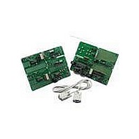
... Sample programs 4. PICDEM LIN Demonstration Board User’s Guide (this document) Note: Please contact your nearest Microchip sales office for any missing parts from the kit. FIGURE 1-1: 2004 Microchip Technology Inc. ™ PICDEM LIN USER’S GUIDE ™ LIN Introduction ® ...
Page 6
... PICDEM LIN up and running as a stand-alone board. Chapter 3: Tutorials – This chapter provides a detailed description of the tutorial programs. Appendix A: Hardware Detail - This appendix describes in detail the hardware of the PICDEM LIN board. DS41185C-page 2 ® MCUs supported. 2004 Microchip Technology Inc. ...
Page 7
... PRO MATE ® • MPLAB ICE Emulator User’s Guide (DS51159) ® • PICmicro Mid-Range Reference Manual (DS33023) • LIN bus Specification Ver. 1.2 (can be obtained from www.lin-subbus.de) 2004 Microchip Technology Inc. ™ PICDEM II User’s Guide (DS30082) LIN Introduction DS41185C-page 3 ...
Page 8
... PICDEM LIN User’s Guide NOTES: DS41185C-page 4 2004 Microchip Technology Inc. ...
Page 9
... Press buttons S8 or S10 on the console panel to see ports on the slave nodes increment or decrement. These steps are illustrated in Figure 2-1. FIGURE 2-1: 12V Supply 2004 Microchip Technology Inc. ™ PICDEM LIN USER’S GUIDE ® MCU compatible emulators, please ...
Page 10
... Verify that the device is blank (e.g., perform a blank check) before attempting to program it. FIGURE 2-3: DS41185C-page 6 FLAT RIBBON CABLE CONNECTION Prototyping Board V BAT LIN GND JP5 Panel 1 FLAT RIBBON CABLE WINDOWED DEVICE Slave Node 1 V BAT LIN GND JP4 Panel 2 2004 Microchip Technology Inc. ...
Page 11
... Zener diode, filtered on both the input and output. An LED is connected to the output for ’power-on’ indication. 2.3.1.2 LIN BUS TRANSCEIVER The Local Interface Network transceiver is socketed to accept an industry standard LIN or K/L-Line transceiver. The Microchip Technology MCP201 can be accommodated by removing the jumper connecting pin 3, V 2004 Microchip Technology Inc. Getting Started TM Assembler available with MPLAB IDE. ® ...
Page 12
... Figure 2-5 shows the configuration where the USART is connected to the LIN bus transceiver chip, RB5 to the Transmit line, and RB4 to the Receive line of the RS-232 chip. FIGURE 2-4: DS41185C-page 8 JUMPER E7 CONNECTS USART TO LIN BUS TRANSCEIVER Jumper E7 1 2004 Microchip Technology Inc. ...
Page 13
... RC oscillator. This is done by unsoldering the crystal and C20, and installing a 10K resistor on R36. This will allow the PICmicro MCU to run off an RC oscillator. 2004 Microchip Technology Inc. USART CONNECTED TO LIN BUS TRANSCEIVER, RB4 AND RB5 TO MAX RS-232 ...
Page 14
... RB5 and a LED is routed to RB2. A high voltage tolerant input is routed to RB1. 2.3.4.1 RF RECEIVER The RF receiver is a standard Telecontrolli module, as supplied in the K development kits. The module installed is for 433.9 MHz. DS41185C-page 10 when closed, and DD when DD and turned on by taking the DD OQ ® 2004 Microchip Technology Inc. ...
Page 15
... PICmicro MCU in-circuit without removing it from the board. When the ICSP interface is used for In-Circuit-Debug (ICD), RB3, RB6 and RB7 are no longer available to the user on 28- and 40-pin devices. Motor control headers J9 and J15 should not be used. 2004 Microchip Technology Inc. ® microcontroller. Position ...
Page 16
... If some of the I/O pins from PORTB are to be connected to the high-side driver, the respective Jumpers E10 to E17 should be removed and a connection has to be established on the Jumper Field J19. Analog inputs to PORTA pins are provided through Connector JP11. The schematic of this board is given in Figure A-7. DS41185C-page 12 2004 Microchip Technology Inc. ...
Page 17
... The calculation is done according to the LIN bus specification, Ver. 1.2. The calculate parity bits are stored in bit 6 and bit 7 of the identifier byte. 2004 Microchip Technology Inc. ™ PICDEM Chapter 3. Tutorial LIN USER’ ...
Page 18
... In Receive mode, all data, including CRC, is received. The CRC value is checked and the routine returns to the main routine. 3.1.1.5 ERROR HANDLING In the example, no error handling is implemented. The LIN bus specification gives the user the flexibility to handle errors. DS41185C-page 14 2004 Microchip Technology Inc. ...
Page 19
... FIGURE 3-1: 2004 Microchip Technology Inc. MAIN ROUTINE OF LIN BUS MASTER Start-up Main Routine Read Keys Generate Parity Bit Generate Checksum Transmit Data via LIN bus Tutorial DS41185C-page 15 ...
Page 20
... After all data is transmitted, the LIN handler routine returns to the main routine. Receive mode After receiving all data received, the CRC value is checked. After the CRC check, the LIN bus handler routine returns to the main routine. DS41185C-page 16 2004 Microchip Technology Inc. ...
Page 21
... FIGURE 3-2: 2004 Microchip Technology Inc. PROGRAM FLOW OF THE PIC16C432 LIN SLAVE CODE Start-up Main Program No Synch Field detected? Yes LIN Handler Receive Message Yes ID=TEST? No Yes ID=WindowUp? Increment PORTB Yes ID=WindowDown? Decrement PORTB No Tutorial Turn on LED connected to RB0 DS41185C-page 17 ...
Page 22
... The Program flow is almost identical to that described in 3.1.2 “The PIC16C432 LIN bus Slave Code”, with the following exceptions: • Pushing the WindowDown button on the console panel will turn on GPIO0 • Pushing the WindowUp button on the console panel will turn off GPIO0 DS41185C-page 18 2004 Microchip Technology Inc. ...
Page 23
... Appendix A. Hardware Detail A.1 BOARD LAYOUT AND SCHEMATICS FIGURE A-1: H-BRIDGE DRIVER GND 2 2004 Microchip Technology Inc. ™ PICDEM LIN USER’S GUIDE DS41185C-page 19 ...
Page 24
... PICDEM LIN User’s Guide FIGURE A-2: HIGH-SIDE DRIVER GND 2 DS41185C-page 20 HCVbat PWROUT1 16 15 PWREN 14 13 PWROUT2 12 11 GND 2004 Microchip Technology Inc. 1 ...
Page 25
... FIGURE A-3: GENERAL PROTOTYPING BOARD GND 2 2004 Microchip Technology Inc. HCVbat VBAT Hardware Detail DS41185C-page 21 ...
Page 26
... PICDEM LIN User’s Guide FIGURE A-4: H-BRIDGE DRIVER BOARD 1 GND 2 DS41185C-page 22 VCC GND 1 7 2004 Microchip Technology Inc. ...
Page 27
... FIGURE A-5: H-BRIDGE DRIVER BOARD 2 GND 2 2004 Microchip Technology Inc. Hardware Detail GND 7 1 DS41185C-page 23 ...
Page 28
... PICDEM LIN User’s Guide FIGURE A-6: INSTRUMENT CONTROL CONSOLE + COM DS41185C-page 2004 Microchip Technology Inc. ...
Page 29
... FIGURE A-7: MASTER NODE AND CAN INTERFACE RB5 RB4 GND 2 2004 Microchip Technology Inc. Hardware Detail BAT HCV V BAT DS41185C-page 25 ...
Page 30
... PICDEM LIN User’s Guide FIGURE A-8: REMOTE KEYLESS ENTRY DECODER VCC 15 OUT 14 TEST 13 VCC 12 GND 11 VCC GND ANT 3 GND 2 VCC 1 GND 2 DS41185C-page 26 VBAT 2004 Microchip Technology Inc. ...
Page 31
... FIGURE A-9: POWER SEAT MEMORY CONTROLLER 2 GND 2 2004 Microchip Technology Inc GND Hardware Detail VBAT DS41185C-page 27 ...
Page 32
... PICDEM LIN User’s Guide NOTES: DS41185C-page 28 2004 Microchip Technology Inc. ...
Page 33
... B.1 LIN bus MASTER CODE The software supplied herewith by Microchip Technology Incorporated (the “Company”) is intended and supplied to you, the Company’s customer, for use solely and exclusively with products manufactured by the Company. The software is owned by the Company and/or its supplier, and is protected under applicable copyright laws. All rights are reserved. ...
Page 34
... No action required, because no key was ; pressed ; counter for LIN Bus bytes ; temporary register for ID byte ; temporary counter register ; number of bytes to receive or transmit ; temporary register ; temporary register ; temporary register ; goto StartUp routine ; no interrupts, therefore goto StartUp routine 2004 Microchip Technology Inc. ...
Page 35
... Reset Data pointer to Start Postion movlw DATAPOINTER movwf FSR ; Transmit LIN Bus Data call l_u8wr_sss EndMainRoutine goto 2004 Microchip Technology Inc. : StartUp : Thomas Schmidt : 1.0 : none : none : none : This routine is called after power-up. PORTS and peripherals are initialized. ; Initialize PORTS and peripherals ...
Page 36
... Send 0x00 ; check if data was send ; data not fully received ; copy data receive into w-register ; check if data transmited is the same like ; data received. ; check zero flag ; result is not the same, therefore an abritration ; error occured ; turn USART off * * * * * * * * * * * * * * * * * * * 2004 Microchip Technology Inc. ...
Page 37
... MESSAGE_COUNTER, f goto TestRXData ; check CRC value call l_checksum 2004 Microchip Technology Inc. ; select Page 1 in order to change baudrate to 19.2Kbaud ; change baudrate to 9.6KBaud @ 4MHz ; change baudrate to 19.2Kbaud @ 4MHz ; select slow rate for 20MHz communication ; change baudrate to 9.6KBaud @ 20MHz (BRGH=0) ; change baudrate ...
Page 38
... PORTA ; reset PORTB ; reset PORTC ; reset PORTD ; reset PORTD ; select page 1 ; make RE0 an output ; make PORTD all inputs ; init TRISD register ; make all pins on portA outputs ; ; make all pin digital IOs ; select page 0 ; turn LED 2004 Microchip Technology Inc. ...
Page 39
... STATUS, RP0 movlw b'00010000' movwf RCSTA bsf RCSTA, SPEN retlw 0x00 2004 Microchip Technology Inc. : RAM Initialization Routine : Thomas Schmidt : 08/14/2001 : 1.0 : none : none : none : This routine initializes RAM (general purpose RAM) ; first address for data ; load into FSR register ...
Page 40
... ID3 into bit0 ; copy TEMP1 into w-register ; TEMP2 = ID1 XOR ID3 ; ID4 into bit0 ; TEMP1 into w-register ; TEMP2 = TEMP2 XOR ID4 ; ID5 into bit0 ; TEMP2 = TEMP2 XOR ID5 ; negate TEMP2 ; check if P1=1 ; P1=1 ; P1=0 ; return ; set P1 ; return to main * * * * * * * * * * * 2004 Microchip Technology Inc. ...
Page 41
... CRCCheck incf FSR, f movf INDF, w addwf TEMP, w xorlw 0xff btfss STATUS, Z 2004 Microchip Technology Inc. : CRC Check and Generation : Thomas Schmidt : 1.0 : none : none : CRC Check :CRC check is appended after last Data Byte * CRC Gen :CRC is check and CRC_OK or CRC_ERROR is ...
Page 42
... LOCK doors key was pressed ; yes, return with LockDoors value ; check if WindowUp key was pressed ; was WindowUp key pressed? ; yes, return with WindowsUp value ; check if WindowsDown key was pressed ; was WindowsDown key pressed? ; yes, return with WindowsDownValue ; No Key was pressed * * * * * * * * * * * * 2004 Microchip Technology Inc. ...
Page 43
... ReloadTemp return ReloadTemp movlw 0xff movwf TEMP1 goto Loop1 ExLoop1 goto Loop1 2004 Microchip Technology Inc. : Delay Routine for 25ms @ 4MHz : Thomas Schmidt : 08/14/2001 : 1.0 : none : none : none : This routine generates a delay for 25ms @ 4MHz ; intialize TEMP1 ; with 0xff ; initialize TEMP2 ...
Page 44
... Receive Data from bus ; Receive data from bus ; Receive data from bus ; Receive Data from bus ; Receive Data from bus ; Receive data from bus ; Receive data from bus ; Receive Data from bus ; Receive Data from bus * * * * * * * * * * * * 2004 Microchip Technology Inc. ...
Page 45
... C.1 LIN bus SLAVE FOR THE PIC16C432 CODE The software supplied herewith by Microchip Technology Incorporated (the “Company”) is intended and supplied to you, the Company’s customer, for use solely and exclusively with products manufactured by the Company. The software is owned by the Company and/or its supplier, and is protected under applicable copyright laws. All rights are reserved. ...
Page 46
... After that the routine receives and transmits incomming characters. ; Call Startup Routine ; Check for synch byte ; Synch byte not received ; check for end of synchbyte ; end of synchronization byte not received ; call LIN bus handler 2004 Microchip Technology Inc. ...
Page 47
... FSR, f decfsz TEMP1, f goto Count retlw 0x00 2004 Microchip Technology Inc. LIN bus Slave for the PIC16C432 ; copy ID_TEMP into w-register ; decode only lower four nibbles ; see if LED has to be turn on ; reset PCLATH register ; add Ignore all other IDs ...
Page 48
... Autobaud low register ; keep on testing ; increment high byte of autobaud register ; keep on testing ; increment Autobaud low register ; keep on testing ; increment high byte of autobaud register ; keep on testing 2004 Microchip Technology Inc. ...
Page 49
... Identifier byte call Receive ; store Identifier byte movf RXTX_REG, w movwf ID_TEMP 2004 Microchip Technology Inc. LIN bus Slave for the PIC16C432 ; check if pin is still high ; no, there was not, measure time ; increment counter register ; check if all 8 bits were received ; ; is result zero? ...
Page 50
... Microchip Technology Inc. ...
Page 51
... STATUS, RP0 bsf LININTF, LINTX bcf STATUS, RP0 call DelayFullBit retlw 0x00 2004 Microchip Technology Inc. LIN bus Slave for the PIC16C432 : LIN bus Receive Routine : Thomas Schmidt : 1.0 : none : none : none : This routine receives an 8-bit value via the LIN Bus ...
Page 52
... TEMP1 ; decrement low byte until zero ; extra two cycle delay ; return from subroutine ; additional two cycle delay ; additional two cycle delay 2004 Microchip Technology Inc. ...
Page 53
... TEMP2, w xorlw 0xff btfss STATUS, Z retlw CRC_ERROR retlw CRC_OK 2004 Microchip Technology Inc. LIN bus Slave for the PIC16C432 : CRC Check and Generation * : Thomas Schmidt* : 08/14/2001* : 1.0* : none* : none* : CRC Check: CRC check is appended after last Data Byte CRC Gen ...
Page 54
... TEMP2 = TEMP2 XOR ID4 ; ID5 into bit0 ; TEMP2 = TEMP2 XOR ID5 ; negate TEMP2 ; check if P1=1 ; check if received P1=1 ; check if P1=0 ; received P1 is not 0 therefore parity error ; received therefore no parity error ; set P1 ; parity error occured ; no parity error occured 2004 Microchip Technology Inc. ...
Page 55
... END 2004 Microchip Technology Inc. LIN bus Slave for the PIC16C432 ; set PCLATH register ; add Receive data from bus ; Receive data from bus ; Receive Data from bus ; Receive Data from bus ; Receive data from bus ...
Page 56
... PICDEM LIN User’s Guide NOTES: DS41185C-page 52 2004 Microchip Technology Inc. ...
Page 57
... D.1 LIN bus SLAVE FOR THE PIC16C432 (SLAVE2.ASM) The software supplied herewith by Microchip Technology Incorporated (the “Company”) is intended and supplied to you, the Company’s customer, for use solely and exclusively with products manufactured by the Company. The software is owned by the Company and/or its supplier, and is protected under applicable copyright laws. All rights are reserved. ...
Page 58
... LIN bus handler ; copy ID_TEMP into w-register ; decode only lower four nibbles ; see if LED has to be turn on ; reset PCLATH register ; add Ignore all other IDs ; Window up function ; Window down function 2004 Microchip Technology Inc. ...
Page 59
... INDF incf FSR, f decfsz TEMP1, f goto Count retlw 0x00 2004 Microchip Technology Inc. ; increment GPIO register ; Go back ; decrement GPIO register ; go back : StartUp : Thomas Schmidt : 1.0 : none : none : none : This routine is called after power-up. PORTS and peripherals are initialized. ...
Page 60
... Autobaud low register ; keep on testing ; increment high byte of autobaud register ; keep on testing ; check if pin is still high ; no, there was not, measure time ; increment counter register ; check if all 8 bits were received ; ; is result zero? ; No, therefore keep on measuring 2004 Microchip Technology Inc. ...
Page 61
... DecDataLength clrf PCLATH movwf MESSAGE_COUNTER incf MESSAGE_COUNTER,f 2004 Microchip Technology Inc. ; adjust low byte ; clear carry bit ; rotate autobaud high register ; rotate autobaud low register ; clear carry bit ; rotate autobaud high register ; rotate autobaud low register ; clear carry bit ...
Page 62
... Microchip Technology Inc. ...
Page 63
... COUNTER, f goto TransmitNext bsf GPIO, LINTX call DelayFullBit retlw 0x00 2004 Microchip Technology Inc. : LIN bus Receive Routine : Thomas Schmidt : 08/14/2001 : 1.0 : none : none : none : This routine receives an 8-bit value via the LIN bus ; clear receive register ; number of bits to receive ...
Page 64
... TEMP1 ; decrement low byte until zero ; extra two cycle delay ; return from subroutine ; additional two cycle delay ; additional two cycle delay 2004 Microchip Technology Inc. ...
Page 65
... STATUS, Z retlw CRC_ERROR retlw CRC_OK 2004 Microchip Technology Inc. : CRC Check and Generation : Thomas Schmidt : 1.0 : none : none : CRC Check: CRC check is appended after last Data Byte CRC Gen : CRC is check and CRC_OK or CRC_ERROR is into the w-register : This routine generates or check CRC based on the Modulo-256 checksum defined in the LIN bus spec ...
Page 66
... TEMP2 = TEMP2 XOR ID4 ; ID5 into bit0 ; TEMP2 = TEMP2 XOR ID5 ; negate TEMP2 ; check if P1=1 ; check if received P1=1 ; check if P1=0 ; received P1 is not 0 therefore parity error ; received therefore no parity error ; set P1 ; parity error occured ; no parity error occured 2004 Microchip Technology Inc. ...
Page 67
... RXMODE retlw RXMODE retlw RXMODE retlw RXMODE retlw RXMODE retlw RXMODE 2004 Microchip Technology Inc. ; Set PCLATH register ; add data length data length data length data length set PCLATH register ; add Receive data from bus ; Receive data from bus ; Receive Data from bus ...
Page 68
... Windows Up ; Windows Down ; Mirror Left ; Mirror Right ; Mirror Down ; Mirror Up ; Tilt Seat Back ; Tilt Seat Forward ; Slide Seat Forward ; Slide Seat Backward ; Front Edge Set Up ; Front Edge Set Down ; Back Edge Seat Up ; Back Edge Seat Down 2004 Microchip Technology Inc. ...
Page 69
... K Keyboard Read Routine ..................................................... 13 L LEDs .................................................................................. 12 LIN bus WWW Address ............................................................. 3 LIN bus Handler ................................................................. 16 Receive Mode ............................................................ 16 2004 Microchip Technology Inc. ™ PICDEM LIN User’s Guide Index Transmit Mode ........................................................... 16 LIN bus Master Code ......................................................... 29 LIN bus Slave for the PIC16C432 (slave2.asm) ................ 53 LIN bus Slave for the PIC16C432 Code ............................ 41 LIN bus Slave Node High-Side Drivers ...
Page 70
... PICDEM LIN User’s Guide S Sample Devices ............................................................... 1, 2 Sample Programs ................................................................ 1 Stand-Alone Board Sample Devices ........................................................... 6 Sample Programs ........................................................ 6 Switches ............................................................................... 9 T Tutorials ............................................................................. 13 W Windowed Device ................................................................ 6 DS41185C-page 66 2004 Microchip Technology Inc. ...
Page 71
... NOTES: 2004 Microchip Technology Inc. ™ PICDEM LIN User’s Guide DS41185C-page 67 ...
Page 72
... Fax: 65-6334-8850 Taiwan - Kaohsiung Tel: 886-7-536-4816 Fax: 886-7-536-4817 Taiwan - Taipei Tel: 886-2-2500-6610 Fax: 886-2-2508-0102 Taiwan - Hsinchu Tel: 886-3-572-9526 Fax: 886-3-572-6459 2004 Microchip Technology Inc. EUROPE Austria - Weis Tel: 43-7242-2244-399 Fax: 43-7242-2244-393 Denmark - Ballerup Tel: 45-4420-9895 Fax: 45-4420-9910 France - Massy Tel: 33-1-69-53-63-20 ...