DM163008 Microchip Technology, DM163008 Datasheet
DM163008
Specifications of DM163008


Related parts for DM163008

DM163008 Summary of contents
Page 1
... Microchip Technology Inc. MCP2120/MCP2150 DEVELOPER’S KIT USER’S GUIDE DS51246C ...
Page 2
... PowerCal, PowerInfo, PowerMate, PowerTool, rfLAB, rfPICDEM, Select Mode, Smart Serial, SmartTel and Total Endurance are trademarks of Microchip Technology Incorporated in the U.S.A. and other countries. SQTP is a service mark of Microchip Technology Incorporated in the U.S.A. All other trademarks mentioned herein are property of their respective companies. ...
Page 3
... A.2 Power Supply ............................................................................................... 41 A.3 Power Indicator ............................................................................................ 41 A.4 RS-232 Serial Port ....................................................................................... 41 A.5 Jumpers ....................................................................................................... 42 A.6 Oscillator Options ......................................................................................... 44 A.7 Board Layout ................................................................................................ 45 A.8 Schematics .................................................................................................. 46 Index ............................................................................................................................. 49 Worldwide Sales and Service .................................................................................... 50 © 2005 Microchip Technology Inc. MCP2120/MCP2150 DEVELOPER’S KIT USER’S GUIDE Table of Contents DS51246C-page iii ...
Page 4
... MCP2120/MCP2150 Developer’s Kit User’s Guide NOTES: DS51246C-page iv © 2005 Microchip Technology Inc. ...
Page 5
... MCP2120 and MCP2150 infrared communication products. Items discussed in this chapter include: • About This Guide • Recommended Reading • The Microchip Web Site • Customer Support © 2005 Microchip Technology Inc. MCP2120/MCP2150 DEVELOPER’S KIT USER’S GUIDE Preface ® IDE ...
Page 6
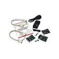
... MCP2120/MCP2150 Developer’s Kit User’s Guide (this document) – not shown. If you are missing any part of the kit, please contact your nearest Microchip sales office listed in the back of this publication for help. FIGURE 1-1: 3 DS51246C-page 2 MCP2120/MCP2150 DEVELOPER’S KIT © 2005 Microchip Technology Inc. ...
Page 7
... Appendix A: Hardware Description – This appendix describes in detail the hardware of the MCP2120 Developer’s board and MCP2150 Developer’s board. This includes the component layout of each board (silkscreen) and the schematic of each board. © 2005 Microchip Technology Inc. Preface DS51246C-page 3 ...
Page 8
... A hexadecimal number where 0xFFFF, 0x007A hexadecimal digit Optional arguments mcc18 [options] file [options] Choice of mutually exclusive errorlevel {0|1} arguments selection Replaces repeated text var_name [, var_name...] Represents code supplied by void main (void) user { ... } © 2005 Microchip Technology Inc. Examples ® IDE User’s Guide ...
Page 9
... Microchip consultant program member listing • Business of Microchip – Product selector and ordering guides, latest Microchip press releases, listing of seminars and events, listings of Microchip sales offices, distributors and factory representatives © 2005 Microchip Technology Inc. Preface ® Standard Wireless Connectivity” (DS00758) ® ...
Page 10
... Microchip's development systems software products. This line also provides information on how customers can receive currently available upgrade kits. The Development Systems Information Line numbers are: 1-800-755-2345 – United States and most of Canada 1-480-792-7302 – Other International Locations DS51246C-page 6 © 2005 Microchip Technology Inc. ...
Page 11
... Jumper to disable MCP2120 device operation. 10. Hardware and Software Baud selection. 11. Jumper for Software Baud control when using RS-232C interface. 12. Socketed crystal. Note: A schematic of the MCP2120 Developer’s Board is shown in Figure A-5 © 2005 Microchip Technology Inc. MCP2120/MCP2150 DEVELOPER’S KIT USER’S GUIDE DS51246C-page 7 ...
Page 12
... JP3:JP1 OSC /768 R14 000 OSC /384 001=F OSC /192 010=F OSC /128 011=F C5 OSC /64 100=F C3 111=S/W Baud Open C11 R15 C18 C6 R3 C10 U4 R5 R10 R11 Component D1 Transceiver R12 8 U6 Integrated Transceiver R13 C16 +5V GND © 2005 Microchip Technology Inc. ...
Page 13
... When the header has the pins closest to the “Component Transceiver” label jumpered to the center pin, the component transceiver logic is used. FIGURE 1-2: J2 These two jumpers select the source of the Host signals. J1 and J4 © 2005 Microchip Technology Inc. MCP2120 SELECTING SOURCES R9 J5 CR1 C4 C15 D4 ...
Page 14
... OSC /128 OSC /64 C16 J3 GND +5V F /128 OSC F /64 OSC Software Baud Mode (2) (2) 20.000 Bit Rate 19200 26042 F OSC / 768 OSC 38400 52083 F / 384 78600 104167 F OSC / 192 115200 156250 F OSC / 128 230400 312500 F OSC / 64 © 2005 Microchip Technology Inc. ...
Page 15
... Hardware Baud operation, or Software Baud operation. When in Software Baud operation, an additional signal is required, Request To Send (RTS), which is used to drive the RESET pin low to cause a change of baud rate to occur. FIGURE 1- UART configuration for Hardware/Software Baud mode © 2005 Microchip Technology Inc. MCP2120 UART R9 J5 CR1 C4 ...
Page 16
... JP4 R4 R5 R10 R11 (MCP2120) Open=Enabled Component D1 Transceiver R12 U6 Integrated JP3:JP1 Transceiver OSC /768 000=F OSC /384 001=F OSC /192 010=F R13 OSC /128 011=F OSC /64 100=F 111=S/W Baud C16 Open=0 J3 GND +5V Host Controller I/O Pin © 2005 Microchip Technology Inc. ...
Page 17
... Note: A schematic of the MCP2150 Developer’s Board is shown in Figure A-6 FIGURE 1-7: MCP2150 BOARD HARDWARE 1 BT1 U5 C17 D4 J6 C15 C10 J5 MCP2150 Dev Board 02-01609 Rev © 2005 Microchip Technology Inc. 7 Power JP3 CR1 (MCP2150) Open=Enabled C12 C16 R4 R3 JP2 JP1 C4 C2 ...
Page 18
... Both jumpers should connect the same pin positions J7 and J8 Header is source. DB9 is source C11 JP3 R5 R6 C13 R14 Component Transceiver R10 Integrated Transceiver 0 9600 1 19200 R11 R13 C16 0 57600 1 115200 +5VGND Component Transceiver Integrated Transceiver © 2005 Microchip Technology Inc. ...
Page 19
... Figure 1-9 shows the two Baud Rate Select jumpers (JP2:JP1) and the baud rate. Table 1-2 shows the baud rates for some crystal frequencies. FIGURE 1- These three jumpers select the Baud Rate TABLE 1-2: BAUD1:BAUD0 © 2005 Microchip Technology Inc. MCP2150 BAUD RATE BT1 U5 C17 CR1 C12 C15 C16 ...
Page 20
... D1 R2 JP3 R5 R6 C13 (MCP2150) R14 Component Open=Enabled Transceiver R10 JP2 JP1 U6 Integrated Transceiver 0 0 9600 0 1 19200 R11 R13 C16 1 0 57600 1 1 115200 +5VGND Host Controller I/O Pin (High or Hi Impedance = Enabled Low = Disabled) © 2005 Microchip Technology Inc. ...
Page 21
... Hyperterminal. Windows 2000 considers the IrDA port network device. Applications that can access a network service through a network protocol (i.e., TCP/IP) can use the MCP2120 Developer’s Board using the appropriate Windows 2000 driver. © 2005 Microchip Technology Inc. CONFIGURATIONS FOR EVALUATION OF DEVELOPER’S BOARDS ↔ ...
Page 22
... Hyperterminal, that connects the IR port to a virtual serial port. DS51246C-page 18 Developer’s Board #2 ↔ MCP2120 Dev Board (ASCII) Developer’s Board #2 → MCP2120 Dev Board (IR Driver) Developer’s Board #2 ↔ MCP2120 Dev Board (IR Driver) © 2005 Microchip Technology Inc. ...
Page 23
... Hyperterminal. Windows 2000 considers the IrDA port network device. Applications that can access a network service through a network protocol (i.e., TCP/IP) can use the MCP2120 Developer’s Board using the appropriate Windows 2000 driver. © 2005 Microchip Technology Inc. Getting Started Developer’s Board #2 → ...
Page 24
... MCP2120/MCP2150 Developer’s Kit User’s Guide NOTES: DS51246C-page 20 © 2005 Microchip Technology Inc. ...
Page 25
... Figure 2- assumed that two PCs will be used, and that each PC will have the Terminal Emulation program configured identically. FIGURE 2-1: SYSTEM BLOCK DIAGRAM MCP2120 Developer’s PC © 2005 Microchip Technology Inc. MCP2120/MCP2150 DEVELOPER’S KIT USER’S GUIDE MCP2120 Developer’s Board 1 Board 2 ...
Page 26
... J6 and J7 DB9 is source. C11 R15 C18 C6 R3 C10 U4 JP4 R4 R5 R11 R10 (MCP2120) Open=Enabled Component D1 Transceiver R12 U6 Integrated Transceiver OSC /768 OSC /384 OSC /192 R13 OSC /128 OSC /64 C16 J3 GND +5V Integrated Transceiver © 2005 Microchip Technology Inc. ...
Page 27
... MCP2120 operational frequency). The tutorial requires these jumpers to be open for a baud rate of 9600, when the crystal frequency is 7.3728 MHz. FIGURE 2-3: J2 These three jumpers select the Baud Rate JP3:JP2:JP1 © 2005 Microchip Technology Inc. MCP2120 BAUD RATE R9 J5 CR1 C4 C15 ...
Page 28
... Rev MCP2120 Enable/Disable Hardware Baud Selection C11 R15 C18 C6 R3 C10 U4 JP4 R4 R5 R10 R11 (MCP2120) Open=Enabled Component D1 Transceiver R12 U6 Integrated Transceiver OSC /768 OSC /384 OSC /192 R13 OSC /128 OSC /64 C16 J3 +5V GND Enabled © 2005 Microchip Technology Inc. ...
Page 29
... FIGURE 2-5: For the initial test, we will set up the system to operate at 9600 baud. Type the name as shown in Figure 2-6 and select any icon. Click OK. FIGURE 2-6: © 2005 Microchip Technology Inc. MCP2120 Tutorial ® HYPERTERMINAL OPENING SCREEN ...
Page 30
... The menu in Figure 2-7 appears. You will need to select the port your serial port is on (Connect using). In our case, we are using COM1. Click OK. FIGURE 2-7: The Default settings for COM1 are displayed in Figure 2-8. FIGURE 2-8: DS51246C-page 26 SELECTING COMMUNICATIONS (COM) PORT ® HYPERTERMINAL DEFAULT COM PORT SETTINGS © 2005 Microchip Technology Inc. ...
Page 31
... The COM port settings need to be modified so the Bits per second is “9600” and the Flow Control is “None”, as shown in Figure 2-9. Click OK when done. FIGURE 2-9: The terminal window opens connected to the serial port as shown in Figure 2-10. FIGURE 2-10: © 2005 Microchip Technology Inc. MCP2120 Tutorial ® DESIRED HYPERTERMINAL COM PORT SETTINGS ® ...
Page 32
... Figure 2-11. FIGURE 2-11: To modify the properties of this Hyperterminal session, select File > Properties as shown in Figure 2-12. FIGURE 2-12: DS51246C-page 28 DISCONNECTING HYPERTERMINAL ® SELECTING HYPERTERMINAL ® PROPERTIES MENU © 2005 Microchip Technology Inc. ...
Page 33
... Verify the settings are as desired. If not, change the settings to match the settings in Figure 2-14. Click the OK button and you will return to the window shown in Figure 2-13. FIGURE 2-14: © 2005 Microchip Technology Inc. MCP2120 Tutorial ® HYPERTERMINAL PROPERTIES MENU (CONNECT TO) ...
Page 34
... This will make viewing information in the Hyperterminal window more convenient. FIGURE 2-15: Clicking on the “Input Translation...” button will bring up the following window. Click Cancel to close this window. FIGURE 2-16: DS51246C-page 30 ® HYPERTERMINAL PROPERTIES MENU (SETTINGS) INPUT TRANSLATION MENU © 2005 Microchip Technology Inc. ...
Page 35
... Hyperterminal window should have the same character string appear in the Hyperterminal window of PC #1. Congratulations! You may now start modifying the system to evaluate/test the operation of the MCP2120 and MCP2120 Developer’s Board. © 2005 Microchip Technology Inc. MCP2120 Tutorial ASCII SETUP MENU DS51246C-page 31 ...
Page 36
... Figure 2-20 shows the steps for the receive side of System #2 (PC #2 and MCP2120 Developer’s Board #2). These steps can then be used to debug the transmit side of System #2 and the receive side of System #1. DS51246C-page MCP2120 Developer’ Board # Rev. 02-01608 Board Developer’s MCP2120 © 2005 Microchip Technology Inc. ...
Page 37
... Ensure jumper JP4 is open Ensure crystal oscillator is correct frequency and operating Ensure Baud Rate is correct (jumpers JP1, JP2 and JP3) Try replacing with new MCP2120 © 2005 Microchip Technology Inc. DEBUG FLOWCHART – MCP2120 DEVELOPER’S BOARD #1 SIDE Debug Board #1 ® window ...
Page 38
... No MAX232 T1IN pin? Verify 3 pin header J4 Yes is jumpered correctly Data appear on No MAX232 T1OUT pin? Yes Disconnect serial cable to ensure T1OUT is not loaded down. If still no data, it appears ® that the MAX232 device Plus). is damaged © 2005 Microchip Technology Inc. ...
Page 39
... MCP2150 Developer’s Board with an MCP2120 Developer’s Board. Information on Microchip Development Tools can be located on the web site by using the Navigate window and selecting Developer’s Tool Box > Development Tools. © 2005 Microchip Technology Inc. MCP2120/MCP2150 DEVELOPER’S KIT USER’S GUIDE DS51246C-page 35 ...
Page 40
... MCP2120/MCP2150 Developer’s Kit User’s Guide NOTES: DS51246C-page 36 © 2005 Microchip Technology Inc. ...
Page 41
... UART, or the UART functionality may be implemented in software. Figure 4-1 shows the parts layout (silk-screen) for the PICDEM 1 board. FIGURE 4- Note 1: © 2005 Microchip Technology Inc. MCP2120/MCP2150 DEVELOPER’S KIT USER’S GUIDE PICDEM™ 1 PARTS LAYOUT PORT ...
Page 42
... PortB can be used to display received characters, while any of the other ports would be used for the UART and control signals. A PICmicro microcontroller may be selected that has a hardware UART, or the UART functionality may be implemented in software. Figure 4-2 shows the parts layout (silk-screen) for the PICDEM 2 board. DS51246C-page 38 © 2005 Microchip Technology Inc. ...
Page 43
... Information on Microchip Development Tools can be located by using the Navigate window and selecting Developer’s Tool Box > Development Tools. The PICDEM 2 User’s Guide literature number is DS30374, and the PICDEM 2 kit can be ordered with part number DM163002. © 2005 Microchip Technology Inc. PORT B PWR J6 ...
Page 44
... MCP2120/MCP2150 Developer’s Kit User’s Guide NOTES: DS51246C-page 40 © 2005 Microchip Technology Inc. ...
Page 45
... A MAX3238E compatible level shifting IC has been provided with all necessary hardware to support connection of a RS-232 host through the DB-9 connector. The port can be connected using a straight through cable. Refer to the MCP2120 Data Sheet for more information. © 2005 Microchip Technology Inc. MCP2120/MCP2150 DEVELOPER’S KIT USER’S GUIDE DS51246C-page 41 ...
Page 46
... OSC /768 R14 000 OSC /384 001=F OSC /192 010=F OSC /128 011=F C5 OSC /64 100=F C3 111=S/W Baud Open C11 R15 C18 C6 R3 C10 U4 JP4 R5 R10 R11 Component D1 Transceiver R12 3 U6 Integrated Transceiver R13 C16 J3 +5V GND 2 © 2005 Microchip Technology Inc. ...
Page 47
... Three jumpers to select source of UART signals. Either RS-232C socket or the eight-pin header. 2. Two jumpers to select desired baud rate. 3. Two jumpers to select IR Transceiver options. 4. Jumper to disable device operation. FIGURE A- MCP2150 Dev Board 02-01609 Rev. 1 © 2005 Microchip Technology Inc. MCP2150 DEVELOPER’S BOARD HARDWARE BT1 Power C17 JP3 ...
Page 48
... OSC OSC Frequency (MHz) (2) (2) 14.7456 20.000 6400 9600 19200 26042 12800 19200 38400 52083 25600 38400 78600 104167 38400 57600 115200 156250 78600 115200 230400 312500 Frequency - 11.0592 MHz OSC 9600 19200 57600 115200 © 2005 Microchip Technology Inc. ...
Page 49
... BOARD LAYOUT Figure A-3 shows the component layout (silkscreen) for the MCP2120 Board. FIGURE A-3: J2 Figure A-4 shows the component layout (silkscreen) for the MCP2150 Board. FIGURE A- © 2005 Microchip Technology Inc. MCP2120 DEVELOPER’S BOARD COMPONENT LAYOUT R9 J5 CR1 C4 C15 D4 ...
Page 50
... MCP2120/MCP2150 Developer’s Kit User’s Guide A.8 SCHEMATICS Figure A-5 shows the schematic for the MCP2120 Developer’s Board. Figure A-6 shows the schematic for the MCP2150 Developer’s Board. FIGURE A-5: MCP2120 DEVELOPER’S BOARD SCHEMATIC DS51246C-page 46 © 2005 Microchip Technology Inc. ...
Page 51
... FIGURE A-6: MCP2150 DEVELOPER’S BOARD SCHEMATIC © 2005 Microchip Technology Inc. Hardware Detail DS51246C-page 47 ...
Page 52
... MCP2120/MCP2150 Developer’s Kit User’s Guide NOTES: DS51246C-page 48 © 2005 Microchip Technology Inc. ...
Page 53
... MCP2150 Developer’s Board Component Transceiver .................................. 14 Hardware Baud Selection ................................ 13 IR Transceiver ........................................... 13 Selecting Baud Rate ........................................ 15 UART Interface ................................................ 13 MCP2150 Tutorial ................................................... 35 Microchip Web Site ................................................... 5 © 2005 Microchip Technology Inc. MCP2120/MCP2150 DEVELOPER’S KIT USER’S GUIDE Index O Oscillator Options MCP2120 Developer’s Board .......................... 44 MCP2150 Developer’s Board .......................... Requirements ...
Page 54
... Fax: 65-6334-8850 Taiwan - Kaohsiung Tel: 886-7-536-4818 Fax: 886-7-536-4803 Taiwan - Taipei Tel: 886-2-2500-6610 Fax: 886-2-2508-0102 Taiwan - Hsinchu Tel: 886-3-572-9526 Fax: 886-3-572-6459 © 2005 Microchip Technology Inc. EUROPE Austria - Weis Tel: 43-7242-2244-399 Fax: 43-7242-2244-393 Denmark - Ballerup Tel: 45-4420-9895 Fax: 45-4420-9910 France - Massy Tel: 33-1-69-53-63-20 ...