27297 Parallax Inc, 27297 Datasheet - Page 138
27297
Manufacturer Part Number
27297
Description
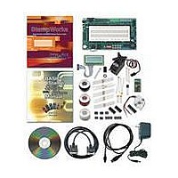
KIT STAMPWORKS WITH BS2-IC
Manufacturer
Parallax Inc
Datasheet
1.27297.pdf
(230 pages)
Specifications of 27297
Lead Free Status
Contains lead
Product
Microcontroller Accessories
Lead Free Status / Rohs Status
Lead free / RoHS Compliant
Available stocks
Company
Part Number
Manufacturer
Quantity
Price


' -----[ Subroutines ]-----------------------------------------------------
Show_Level:
Behind the Scenes
While most BASIC Stamp applications will deal with digital signals, some will require
analog output; a variable voltage between zero and some maximum voltage. The
BASIC Stamp’s PWM instruction is designed to generate an analog voltage when
combined with an R/C filter. The PWM instruction produces a series of pulses which
have a programmable on-time to off-time ratio (duty cycle). The output voltage of
the circuit corresponds directly to the
larger value for
the capacitor to five volts.
In order to ensure that the capacitor is properly charged, the
should be set to at least five R/C time constants. In the circuit above, one time
constant is one millisecond (10 kΩ x 0.1 µF), so setting the
milliseconds guarantees the capacitor will be changed to the level set by
In this experiment, one half of the LM358 is configured as a voltage follower and
serves to provide a buffered output to the LED or other circuitry. The op-amp buffer
prevents the capacitor from discharging too quickly under load. The LED brightens
and dims because the changing voltage through its series resistor changes the
current through the LED. Notice that the LED seems to snap on and get brighter,
then dim to some level and snap off. This happens when the output of the LM358
crosses the forward voltage threshold (the minimum voltage for the LED to light) of
the LED (about 2.3 volts for the blue LEDs on the PDB – other LEDs will differ).
mVolts = level */ $139B
DEBUG CRSRXY, 10, 2,
RETURN
DEC level, CLREOL,
CRSRXY, 10, 3,
DEC1 (mVolts / 1000), ".", DEC3 mVolts
Duty
will result in a higher output voltage. A
Duty
parameter of the PWM instruction – a
' level * 19.6 mV
Duty
Duration
of 255 will charge
Duration
Duty
parameter
.
to 10
Related parts for 27297
Image
Part Number
Description
Manufacturer
Datasheet
Request
R


Part Number:
Description:
Microcontroller Modules & Accessories DISCONTINUED BY PARALLAX
Manufacturer:
Parallax Inc

Part Number:
Description:
BOOK UNDERSTANDING SIGNALS
Manufacturer:
Parallax Inc
Datasheet:


Part Number:
Description:
COMPETITION RING FOR SUMOBOT
Manufacturer:
Parallax Inc
Datasheet:


Part Number:
Description:
TEXT INFRARED REMOTE FOR BOE-BOT
Manufacturer:
Parallax Inc
Datasheet:
Part Number:
Description:
BOARD EXPERIMENT+LCD NX-1000
Manufacturer:
Parallax Inc
Datasheet:

Part Number:
Description:
CONTROLLER 16SERVO MOTOR CONTROL
Manufacturer:
Parallax Inc
Datasheet:

Part Number:
Description:
BASIC STAMP LOGIC ANALYZER
Manufacturer:
Parallax Inc
Datasheet:

Part Number:
Description:
IC MCU 2K FLASH 50MHZ SO-18
Manufacturer:
Parallax Inc
Datasheet: