PC7501 Renesas Electronics America, PC7501 Datasheet
PC7501
Specifications of PC7501


Related parts for PC7501


PC7501 Summary of contents
Page 1
... PC7501 Supported Devices: M16C / R8C Family All information contained in these materials, including products and product specifications, represents information on the product at the time of publication and is subject to change by Renesas Electronics Corporation without notice. Please review the latest information published by Renesas Electronics Corporation through various means, including the Renesas Electronics Corporation website (http://www ...
Page 2
All information included in this document is current as of the date this document is issued. Such information, however, is subject to change without any prior notice. Before purchasing or using any Renesas Electronics products listed herein, please confirm ...
Page 3
... Renesas Electronics Corporation 1753, Shimonumabe, Nakahara-ku, Kawasaki, Kanagawa, 211-8668, Japan Renesas Solutions Corp. Nippon Bldg., 2-6-2, Ote-machi, Chiyoda-ku, Tokyo 100-0004, Japan Renesas Electronics Europe Limited Dukes Meadow, Millboard Road, Bourne End, Buckinghamshire, SL8 5FH, U.K. Renesas PC7501 h ttp://www.renesas.com/weee ” ...
Page 4
... Their graphic images and meanings are given in Chapter 1, Precautions for Safety. Be sure to read this chapter before using the product. • When using this product in Europe, the United States, and Canada, be sure to use the emulator PC7501 and the emulation probe M3xxxxTx-EPB or R0ExxxxxxEPB00 which meet the overseas standards. ...
Page 5
... N ote for LAN Interface: ............................................................................................................................. ote for Using Memory Expansion and Microprocessor Modes ote for Clock: .......................................................................................................................................... hapter 2 PC7501 System Configuration Packing List ............................................................................................................................................ Outline of PC7501 System Configuration PC7501 System Configuration .3.1 Host Machine . .................................................................................................................................. .3.2 Emulator PC7501 ............................................................................................................................ .3.3 Emulation Probe M3xxxxTx-EPB or R0ExxxxxxEPB00 .3.4 Emulator Debugger M3T-PDxxF ...
Page 6
... C hapter 6 Maintenance and Guarantee User Registration ................................................................................................................................... Maintenance ........................................................................................................................................... Guarantee .............................................................................................................................................. Repair Provisions ................................................................................................................................... How to Make Request for Repair hapter 7 External Dimensions & Interface Cable Specifications External Dimensions of the Emulator PC7501 LPT Parallel Interface Cable T U R20UT0207EJ0500 Rev.5.00 Nov 01, 2010 .............................................................................................. .......................................................................................................... .......................................................................................................... ................................................................................. .......................................................................... ........................................................................................... ..................................................................................................................... ..................................................................................................... ...
Page 7
... This means a software tool, M3T-PDxxF to control the emulator PC7501 from a personal computer through an interface. Firmware This means a program that controls the hardware of the PC7501 system by decoding the contents of communication with the emulator debugger M3T-PDxxF. This program is contained in EEPROM on the emulator PC7501's inside board. ...
Page 8
... PC7501 User’s Manual User Registration When you install debugger software, a text file for user registration is created on your PC. Fill it in and email it to your local distributor. If you have replaced an emulator main unit or emulation probe, rewrite an emulator name and serial number in the text file you filled in earlier to register your new hardware products. ...
Page 9
... PC7501 User’s Manual Chapter 1 Precautions for Safety This chapter describes the handling precautions to be followed when using the emulator PC7501. For precautions on using the emulator debugger M3T-PDxxF and emulation probe M3xxxxTx-EPB or R0ExxxxxxEPB00, refer to each user's manual (or Online Help) of them. 1.1 Safety Symbols and Meanings ...
Page 10
... PC7501 User’s Manual Warnings for AC Power Supply: • If the attached AC power cable does not fit the receptacle, do not alter the AC power cable and do not plug it forcibly. Failure to comply may cause electric shock and/or fire. • Use an AC power cable which complies with the safety standard of the country. ...
Page 11
... Caution for Installation: • When in use do not place the emulator PC7501 on its side. Caution for Communication Interface: • Always make sure that the emulator PC7501's interface selection switch and the emulator debugger M3T-PDxxF's interface settings are matched. Cautions to Be Taken for Disposal: • ...
Page 12
... Notes for Unusual Operation: • Do not turn off the power when executing the self-check or downloading firmware. If the emulator PC7501 is powered off in the middle of a process, it will become unable to start up normally. In cases when the power is inadvertently shut off, re-execute the self-check or downloading. ...
Page 13
... Notes for USB Interface: • USB interface can not be used with a host machine running Windows 95 or Windows NT 4.0. • With the USB interface of the PC7501, not all hardware (such as host machine, USB devices, USB hub) combinations will work and are guaranteed. ...
Page 14
... PC7501 User’s Manual MEMO R20UT0207EJ0500 Rev.5.00 Nov 01, 2010 1. Precautions for Safety Page ...
Page 15
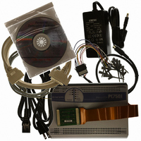
... LPT parallel interface cable (1.9 m, IEEE1284-A male to IEEE1284-C male) • External trigger input/event output cable (50 cm) • 160-pin flexible cable for connecting emulation probe (Preinstalled to PC7501) • Converter board for connecting emulation probe M3T-FLX160-EPB (Preinstalled to PC7501) • Oscillator board OSC-3 for 30 MHz (Preinstalled to PC7501) • ...
Page 16
... PC7501 User’s Manual 2.2 Outline of PC7501 System Configuration The PC7501 system is configured with the following products: (1) Host machine Personal computer (Separately available) (2) Emulator PC7501 (3) Emulation probe M3xxxxTx-EPB or R0ExxxxxxEPB00 (Separately available) (4) Emulator debugger M3T-PDxxF (included) (5) AC adapter (included) Figure 2.1 shows the PC7501 system configuration. ...
Page 17
... The PC7501 is an emulator for Renesas MCUs. The emulator PC7501 has LED indicators on its upper panel to indicate the status of the target MCU and the conditions of the emulator. The emulator PC7501 is controlled by the emulator debugger M3T-PDxxF running on the host machine connected to the host machine via a LAN interface, USB interface or LPT parallel interface ...
Page 18
... Available memory and the required wait states depend on the target MCU. (For details, see an emulation probe user's manual.) *3 The number of user-settable hardware break points depends on the specifications of the emulator debugger M3T-PDxxF. *4 For details of the external dimensions, refer to "7.1 External Dimensions of the Emulator PC7501" (P.45). R20UT0207EJ0500 Rev.5.00 Nov 01, 2010 M16C Family and R8C Family (32/16-bit or 16-bit ...
Page 19
... PC7501 User’s Manual Chapter 3 External View 3.1 Names and Functions of Parts on the Upper Panel Figure 3.1 shows the name and function of each switch and indicator on the upper panel of the emulator PC7501. Figure 3.1 Front panel of the emulator PC7501 R20UT0207EJ0500 Rev.5.00 Nov 01, 2010 3 ...
Page 20
... PC7501 User’s Manual 3.1.1 System Status LEDs The system status LEDs indicate the emulator PC7501's power supply, firmware operating status, etc. Table 3.1 lists the definition of each system status LED. T able 3.1 Definition of system status LED T Name ON/OFF ON Emulator PC7501 power supply is turned on. ...
Page 21
... PC7501 User’s Manual The status of LEDs on the upper panel when the PC7501 emulator system has been started up normally is shown in Figure 3.2 below. Check this when you actually start up the emulator system. Figure 3.2 LED display when system has started up normally Note for Using Memory Expansion and Microprocessor Modes: • ...
Page 22
... HUB, use a straight cable. 3.2.5 Power Supply Switch The power switch of the emulator PC7501 is used to turn the power on and off. Push the switch to the right position (facing the rear panel) to turn on; push the switch to the left position to turn off. ...
Page 23
... If you do not press the switch within two seconds after power-on, the emulator PC7501 and the target MCU are initialized directly, and ready to accept command input for the emulator debugger M3T-PDxxF. Table 3.3 lists the functions of the system reset switch ...
Page 24
... PC7501 User’s Manual 3.3.2 External Trigger Signal Input/Event Output Connectors For the external trigger signal input/event output connector, insert the external trigger signal input/ event output cable shown in Figure 3.6. The external trigger signal input/event output cable is a 9-pin cable, inputs the external trigger signal, and outputs the break signal and event signal ...
Page 25
... IMPORTANT Before making connections, be sure to turn OFF the power to the emulator PC7501 and the host machine. 4.1 Connecting AC Adapter The power is supplied from AC adapter to the emulator PC7501. Here following explains how to connect the AC adapter. Turn OFF the power to the PC7501. Connect the DC cable of AC adapter to the PC7501. ...
Page 26
... Connecting Host Machine When connecting the emulator PC7501 to a host machine, you can choose your desired interface from LPT parallel interface, USB interface and LAN interface. Use the interface selection switch on the emulator PC7501's rear panel to specify your desired interface. ...
Page 27
... Connect the emulation probe M3xxxxTx-EPB or R0ExxxxxxEPB00 and the target system. See the user's manual of the emulation probe T T Turn ON the power to the host machine and then turn ON the power of the PC7501 and the target system as simultaneously as possible. R20UT0207EJ0500 Rev.5.00 Nov 01, 2010 4 ...
Page 28
... PC7501 User’s Manual Figure 4.2 Connecting the LPT parallel interface cable (host machine side) Figure 4.3 Connecting the LPT parallel interface cable (emulator PC7501 side) R20UT0207EJ0500 Rev.5.00 Nov 01, 2010 4. Setup Page ...
Page 29
... Connect the emulation probe M3xxxxTx-EPB or R0ExxxxxxEPB00 and the target system. See the user's manual of the emulation probe T T Turn ON the power to the host machine and then turn ON the power of the PC7501 and the target system as simultaneously as possible. R20UT0207EJ0500 Rev.5.00 Nov 01, 2010 4 ...
Page 30
... PC7501 User’s Manual Figure 4.4 Connecting the USB interface cable (host machine side) Figure 4.5 Connecting the USB interface cable (emulator PC7501 side) R20UT0207EJ0500 Rev.5.00 Nov 01, 2010 4. Setup Page ...
Page 31
... This method can be executed with all the OS's on which the M3T-PDxxF runs. First, use a USB or an LPT parallel interface other than LAN interface to start up the emulator PC7501 and register the network information from the emulator debugger M3T-PDxxF. When the registration of the network information in the emulator PC7501 is completed, you can connect the emulator debugger M3T-PDxxF to the emulator PC7501 by use of the LAN interface ...
Page 32
... PC7501 User’s Manual IMPORTANT If the LAN interface is used as the PC7501 communication interface necessary to acquire an IP address of the PC7501. For details, contact your network administrator. IMPORTANT To register network information, shut power to the PC7501 OFF and restart. The registered information is activated by restarting the PC7501. ...
Page 33
... In incorporating the emulator PC7501 in a network that does not include the host machine, you need to register the IP address of the gateway from the network in which the emulator PC7501 is incorporated to the network in which the host machine is incorporated. You register the IP address of the gateway by means of either step 1 described in "(1) Using the emulator debugger M3T-PDxxF" ...
Page 34
... Note The PC7501 can download firmware over a LAN interface. Note Connecting multiple PC7501's to the same network without registering network information can cause registration errors. Therefore recommended to connect them sequentially one at a time. Note The emulator PC7501 communicates with the host machine using the TCP. ...
Page 35
... PC7501 User’s Manual 4.3 Connecting Emulation Probe M3xxxxTx-EPB or R0ExxxxxxEPB00 The procedure for connecting the emulation probe to the emulator PC7501 is shown below. Turn OFF the power to the emulator PC7501. Connect the converter board M3T-FLX160-EPB of the PC7501 to the emulation probe M3xxxxTx-EPB or R0ExxxxxxEPB00. ...
Page 36
... Set the interface selection switch on the rear panel to "LPT." Connect the LPT parallel interface cable to the emulator PC7501 and the host machine. Within 2 seconds of activating power to the emulator PC7501, press the RESET switch on the front panel. Switched to maintenance mode, the SAFE SYSTEM STATUS LED begins to flash. ...
Page 37
... PC7501 User’s Manual 4.5 Self-check IMPORTANT The self-check is a function to check the memory and other conditions of the emulator PC7501's internal circuit boards. This function can only be executed after the emulator PC7501 is connected to an emulation probe M3xxxxTx-EPB or R0ExxxxxxEPB00. IMPORTANT When executing the self-check, be sure to disconnect the target system. ...
Page 38
... PC7501 User’s Manual MEMO R20UT0207EJ0500 Rev.5.00 Nov 01, 2010 4. Setup Page ...
Page 39
... The USB interface cannot be used with Windows 95 or Windows NT 4.0. □ By the device manager, check the USB driver (musbdrv.sys) is recognized by the host machine. □ Is the PC7501 interface selection switch on the rear panel of the PC7501 set to "USB"? 3.2.1 Interface Selection Switch (P.22 □ ...
Page 40
... PC/EWS on the network to which the PC7501 is connected reply is received, check the network setting of the host machine. □ If the PC7501 and host machine are set to separate networks gateway set in the OS? (192.168.1.254 in the figure below) □ Does an IP address for a gateway registered with the PC7501 specify the gateway that the PC7501 uses? (192 ...
Page 41
... Set the interface selection switch on the rear panel to "LPT." Then, connect the LPT parallel interface cable to the emulator PC7501 and host machine. (2) Within 2 seconds of activating power to the emulator PC7501, press the RESET switch on the front panel to change its mode to maintenance mode. ...
Page 42
... PC7501 User’s Manual 5.5 System Status Error in the Self-check If the self-check does not terminate normally, your system may be malfunctioning. In such a case, consult your local distributor. 6.5 How to Make Request for Repair (P.44) 5.6 How to Request for Support After checking the items in "Chapter 5 Troubleshooting," fill in the text file which is downloaded from the following page, then send the information to your local distributor ...
Page 43
... PC7501 User’s Manual Chapter 6 Maintenance and Guarantee This chapter describes how to maintenance, repair provisions and how to request for repair. 6.1 User Registration When you purchase our product, be sure register as a user. For user registration, refer to “User Registration” (P.8) of this user's manual ...
Page 44
... PC7501 User’s Manual 6.4 Repair Provisions Repairs not covered by warranty The products elapsed more than one year after purchase are not covered by warranty. Replacement not covered by warranty If your product's fault falls in any of the following categories, the fault will be corrected by replacing the entire product instead of repair, or you will be advised to purchase new one, depending on the severity of the fault ...
Page 45
... PC7501 User’s Manual Chapter 7 External Dimensions & Interface Cable Specifications 7.1 External Dimensions of the Emulator PC7501 Figure 7.1 External dimensions of the emulator PC7501 (when attaching the M30830T-FPB) R20UT0207EJ0500 Rev.5.00 Nov 01, 2010 7. External Dimensions & Interface Cable Specifications Unit: mm Page ...
Page 46
... PC7501 User’s Manual 7.2 LPT Parallel Interface Cable The LPT parallel interface connector used for emulator PC7501 is an IEEE1284-C (36-pin half-pitch) connector. Figure 7.2 Pin assignments of connectors and connection of the LPT parallel interface cable R20UT0207EJ0500 Rev.5.00 Nov 01, 2010 7. External Dimensions & Interface Cable Specifications ...
Page 47
... PC7501 User’s Manual MEMO R20UT0207EJ0500 Rev.5.00 Nov 01, 2010 7. External Dimensions & Interface Cable Specifications Page ...
Page 48
... PC7501 User's Manual Publication Date: Nov 01, 2010 Published by: Renesas Electronics Corporation Microcomputer Tool Development Department 2 Edited by: Renesas Solutions Corp. Rev.5.00 ...
Page 49
... SALES OFFICES Refer to "http://www.renesas.com/" for the latest and detailed information. Renesas Electronics America Inc. 2880 Scott Boulevard Santa Clara, CA 95050-2554, U.S.A. Tel: +1-408-588-6000, Fax: +1-408-588-6130 Renesas Electronics Canada Limited 1101 Nicholson Road, Newmarket, Ontario L3Y 9C3, Canada Tel: +1-905-898-5441, Fax: +1-905-898-3220 Renesas Electronics Europe Limited Dukes Meadow, Millboard Road, Bourne End, Buckinghamshire, SL8 5FH, U ...
Page 50
... PC7501 User’s Manual R20UT0207EJ0500 (Previous Number: REJ10J0078-0400) ...