M30290T2-CPE Renesas Electronics America, M30290T2-CPE Datasheet
M30290T2-CPE
Specifications of M30290T2-CPE


Related parts for M30290T2-CPE


M30290T2-CPE Summary of contents
Page 1
To our customers, Old Company Name in Catalogs and Other Documents st On April 1 , 2010, NEC Electronics Corporation merged with Renesas Technology Corporation, and Renesas Electronics Corporation took over all the business of both companies. Therefore, although the ...
Page 2
All information included in this document is current as of the date this document is issued. Such information, however, is subject to change without any prior notice. Before purchasing or using any Renesas Electronics products listed herein, please confirm ...
Page 3
... M30290T2-CPE User’s Manual Compact Emulator for M16C/26A, 28, 29 Groups Rev.2.00 2005.07 ...
Page 4
Keep safety first in your circuit designs! 1. Renesas Technology Corp. puts the maximum effort into making semiconductor products better and more reliable, but there is always the possibility that trouble may occur with them. Trouble with semiconductors may lead ...
Page 5
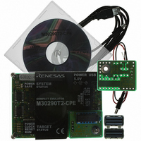
... The M30290T2-CPE is a compact emulator for the M16C/26A, 28, 29 Group MCUs with the real-time trace function. This user's manual mainly describes specifications of the M30290T2-CPE compact emulator and how to setup it. For details on the emulator debugger and C compiler M3T-NC30WA (evaluation version), which are included with the M30290T2-CPE, refer to the online manual. All the components of this product are shown in " ...
Page 6
... M30290T2-CPE User’s Manual Important Before using this product, be sure to read the user’s manual (this user's manual) carefully. Keep this user’s manual, and refer to this when you have questions about this product. Emulator: The emulator in this document refers to the following products that are manufactured by Renesas Technology Corp.: ...
Page 7
... M30290T2-CPE User’s Manual Usage restrictions: This emulator has been developed as a means of supporting system development by users. Therefore, do not use device used for equipment-embedded applications. Also, do not use it for developing the systems or equipment used for the following purposes either: (1) Transportation and vehicular ...
Page 8
... M30290T2-CPE User’s Manual Precautions for Safety Definitions of Signal Words In both the user’s manual and on the product itself, several icons are used to insure proper handling of this product and also to prevent injuries to you or other persons, or damage to your properties. This chapter describes the precautions which should be taken in order to use this product safely and properly. Be sure to read this chapter before using this product ...
Page 9
... M30290T2-CPE User’s Manual Warnings for AC Power Supply: If the attached AC power cable does not fit the receptacle, do not alter the AC power cable and do not plug it forcibly. Failure to comply may cause electric shock and/or fire. Use an AC power cable which complies with the safety standard of the country. ...
Page 10
... M30290T2-CPE User’s Manual Notes on Connecting the Power Supply of the Emulator: Do not use any power cable other than the one that is included with the product. The power cable included with the product has its positive and negative poles color-coded by red and black, respectively ...
Page 11
... M30290T2-CPE User’s Manual Contents Preface..........................................................................................................................................................................3 Important.......................................................................................................................................................................4 Precautions for Safety ..................................................................................................................................................6 Contents........................................................................................................................................................................9 User Registration ........................................................................................................................................................11 Terminology ................................................................................................................................................................12 1. Outline.....................................................................................................................................................................13 1.1 Package Components ...................................................................................................................................13 1.2 System Configuration ....................................................................................................................................14 1.2.1 System Configuration ..........................................................................................................................14 1.2.2 Names and Functions of each part of the Emulator............................................................................15 1.3 Specifications ................................................................................................................................................18 1.4 Operating Environment..................................................................................................................................19 2. Setup.......................................................................................................................................................................20 2.1 Flowchart of Starting Up the Emulator ..........................................................................................................20 2 ...
Page 12
... M30290T2-CPE User’s Manual 4. Hardware Specifications .........................................................................................................................................67 4.1 Target MCU Specifications............................................................................................................................67 4.2 Differences between the Actual MCU and Emulator.....................................................................................68 Note on Differences between the Actual MCU and Emulator ......................................................................68 Note on RESET* Input .................................................................................................................................68 Note on NMI* Input.......................................................................................................................................68 Notes on Maskable Interrupts ......................................................................................................................68 Note on DMA Transfer .................................................................................................................................68 Note on Access Prohibited Area ..................................................................................................................69 Notes on Stack Area ...
Page 13
... M30290T2-CPE User’s Manual User Registration When you have purchased the emulator presented in this user's manual, please be sure to register it. As the H/W Tool Customer Registration Sheet is included with this manual, fill it in and FAX it to your local distributor or email the same contents to the following address ...
Page 14
... Workshop to control the emulator for the M16C family. Firmware This means a program stored in the flash ROM of the emulator. It analyzes contents of communication with the emulator debugger and controls the emulator M30290T2-CPE. This program is downloadable from the emulator debugger to upgrade firmware or to support other MCUs. Host machine This means a personal computer used to control the M30290T2-CPE emulator system ...
Page 15
... C compiler M3T-NC30WA V.5.30 Release 02 (evaluation version) * Please keep the M30290T2-CPE’s packing box and cushion material in your place for reuse at a later time when sending your product for repair or other purposes. Always use these packing box and cushion material when transporting this product ...
Page 16
... M30290T2-CPE User’s Manual 1.2 System Configuration 1.2.1 System Configuration Figure 1.1 shows a configuration of the M30290T2-CPE system. Host machine (not included) Figure 1.1 System configuration (1) Compact emulator M30290T2-CPE (this product) This is a compact emulator for the M16C/26A, 28, 29 Groups with the real-time trace functions (hereafter, emulator). The M30290T-EPBM on which an evaluation MCU is mounted can be also purchased separately ...
Page 17
... LED5: MCU RESET pin (RESET) LED6: Program execution (RUN) Figure 1.2 Names of the LEDs on the upper panel of the M30290T2-CPE (1) System Status LEDs The system status LEDs indicate the emulator main unit’s operating status etc. Table 1.2 lists the definition of the system status LEDs ...
Page 18
... M30290T2-CPE User’s Manual (2) Target Status LEDs The target status LEDs indicate the target MCU’s power supply and operating status. Table 1.3 lists the definition of each target status LED. Table 1.3 Definitions of the target status LEDs Name Number Color Status ...
Page 19
... M30290T2-CPE User’s Manual (6) MCU Power Supply Source Selection Jumper (JP1) This is a jumper switch to set the power supply source to the MCU. For details on this switch, see “2.6.1 MCU Power Supply Source Selection Jumper/MCU Power Supply Voltage Selection Jumper” (page 24). ...
Page 20
... M30290T2-CPE User’s Manual 1.3 Specifications Table 1.5 lists specifications of the M30290T2-CPE. Table 1.5 M30290T2-CPE specifications Applicable MCUs Evaluation MCU Usable mode Maximum operating frequency Applicable power supply Basic debugging functions Real-time trace function Real-time RAM monitor function Hardware break function ...
Page 21
... M30290T2-CPE User’s Manual 1.4 Operating Environment Be sure to use this emulator with the operating environmental of the emulator and host machine listed in Tables 1.6 and 1.7. Table 1.6 Operating environmental conditions Item Operating temperature Storage temperature Table 1.7 Operating environment of the host machine ...
Page 22
... M30290T2-CPE User’s Manual 2. Setup This chapter describes the preparation for using this product, the procedure for starting up the emulator and how to change settings. 2.1 Flowchart of Starting Up the Emulator The procedure for starting up the emulator is shown in Figure 2.1. For details, refer to each section hereafter. And, when the emulator does not start up normally, refer to “ ...
Page 23
... M30290T2-CPE User’s Manual 2.2 Installing the Included Software If the OS used in your host machine is Windows XP or 2000, this installation must be executed by a user with administrator rights. Be aware that users without administrator rights cannot complete the installation. The "auto_run.exe" starts up by inserting the included CD into the CD-ROM drive, and the HTML page for installation will open. Install the C compiler, emulator debugger and USB driver as occasion demands. In process of installation, “ ...
Page 24
... M30290T2-CPE User’s Manual 2.4 Connecting the Power Supply for the Emulator Connect the power supply for the emulator to the power connector (J1). The specification of the power supply for the emulator is listed in Table 2.1. Table 2.1 Specification of power supply of the emulator DC 5.0 V±5%/2 A Power supply voltage Figures 2 ...
Page 25
... M30290T2-CPE User’s Manual 2.5 Connecting the Host Machine Connect the emulator and the host machine with the USB interface cable. Connect the USB interface cable (included) to the USB interface connector (J2) and the USB port of the host machine (see Figure 2.5). ...
Page 26
... M30290T2-CPE User’s Manual 2.6 Turning ON the Power 2.6.1 MCU Power Supply Source Selection Jumper/MCU Power Supply Voltage Selection Jumper Set the MCU power supply source selection jumper and the MCU power supply voltage selection jumper of the emulator according to conditions of use. ...
Page 27
... M30290T2-CPE User’s Manual 2.6.2 Checking Connections of the Emulator System Before turning the power ON, check the connection of the interface cable to the host machine, emulator, and user system. 2.6.3 Turning ON/OFF the Power Turn ON/OFF the power of the emulator and user system as simultaneously as possible. ...
Page 28
... M30290T2-CPE User’s Manual 2.6.5 LED Display When the Emulator Starts Up Normally After the emulator starts up, check the status of the LEDs to see whether the emulator operation is enabled or not. Figure 2.7 shows the positions of the emulator status LEDs. System status LEDs Target status LEDs Figure 2 ...
Page 29
... M30290T2-CPE User’s Manual When the user system connected : If the POWER LED does not light, shut off the system and check the setting of the jumper switches and if the power is properly supplied to the user system. Figure 2.9 Target status LEDs display when the emulator starts up normally (when user system connected) Note on the Target Status CLOCK LED: If the LED is not turned on, check the following ...
Page 30
... M30290T2-CPE User’s Manual 2.7 Self-check 2.7.1 Self-check Procedure To run the self-check of the emulator explained here below. While the self-check is in progress, the LEDs will change as shown in Figure 2.10. (1) If the user system is connected, disconnect it. (2) Set the switches as the factory-settings to execute the self-check (see Table 2.3). ...
Page 31
... M30290T2-CPE User’s Manual 2.7 Error is Detected in the Self-check Table 2.4 lists how to remedy the troubles if the target status LED display is abnormal in the self-check. When an error is detected, shut off the emulator and the user system and follow the steps in the Table 2.4. ...
Page 32
... M30290T2-CPE User’s Manual 2.8 Connecting the User System Figure 2.11 shows the connection of the M30290T2-CPE and the user system. 42-pin 0.8-mm-pitch 0.5-mm-pitch M30263T-42SSB SSOP Socket frame (x2) *1 M3T-SSOP42B-450 *1 Socket main unit *1 Figure 2.11 Connection of the M30290T2-CPE and user system Note on Connecting the User System: Take care not to attach the converter board in a wrong direction ...
Page 33
... M30263T2-CPE-FP). For details on the M30263T-42SSB, refer to its user's manual. (1) Mount the socket included with the M30263T-42SSB to the user system. (2) Attach the M3T-SSOP42B-450 included with the M30263T-42SSB and the socket frame to the socket. (3) Attach the J1 and J2 of the M30290T-PTCB to the J3 and J4 of the M30290T2-CPE. (4) Attach the M30263T-42SSB to the M3T-SSOP42B-450. M30290T-PTCB Figure 2 ...
Page 34
... Mount the NQPACK048SD included with the M30260T-48FPD to the user system. (2) Attach the YQPACK048SD included with the M30260T-48FPD to the NQPACK048SD and secure it with the YQ- GUIDE's. (3) Attach the J1 and J2 of the M30290T-PTCB to the J3 and J4 of the M30290T2-CPE. (4) Attach the M30260T-48FPD to the YQPACK048SD. M30290T-PTCB * Figure 2 ...
Page 35
... Mount the NQPACK064SD-ND included with the M30291T-64FPD to the user system. (2) Attach the YQPACK064SD included with the M30291T-64FPD to the NQPACK064SD-ND and secure it with the YQ- GUIDE's. (3) Attach the J1 and J2 of the M30290T-PTCB to the J3 and J4 of the M30290T2-CPE. (4) Attach the M30291T-64FPD to the YQPACK064SD. M30290T-PTCB * Figure 2 ...
Page 36
... Mount the NQPACK080SD-ND included with the M30290T-80FPD to the user system. (2) Attach the YQPACK080SD included with the M30290T-80FPD to the NQPACK080SD-ND and secure it with the YQ- GUIDE's. (3) Attach the J1 and J2 of the M30290T-PTCB to the J3 and J4 of the M30290T2-CPE. (4) Attach the M30290T-80FPD to the YQPACK080SD. M30290T-PTCB * Figure 2 ...
Page 37
... M30290T2-CPE User’s Manual 2.9 Changing Settings 2.9.1 MCU Power Supply Source Selection Jumper/MCU Power Supply Voltage Selection Jumper These are the jumper switches to select power supply to the MCU and its power voltage. As shown in Table 2.5 below, set the switch according to the connection to the user system. ...
Page 38
... Using an Internal Oscillator Circuit Board 1. Kinds of Oscillator Boards The M30290T2-CPE comes with an oscillator circuit board OSC-3 (20 MHz). And an oscillator circuit bare board OSC-2 is included with this product. If you use an internal oscillator circuit board of the emulator as a main clock, choose "Internal" in the emulator debugger after replacing oscillator circuit boards to change a clock supplied to an MCU. ...
Page 39
... M30290T2-CPE User’s Manual 2. Replacing Oscillator Circuit Boards Figure 2.16 shows how to replace the oscillator circuit boards. POWER USB 5.0V LED1 POWER SYSTEM POWER SAFE STATUS SAFE LED2 5.0V JP2 3.3V EXT JP1 COMPACT EMULATOR INT M30290T2-CPE LED3 POWER POWER CLOCK ...
Page 40
... M30290T2-CPE User’s Manual 3. Using the Internal Oscillator Circuit Bare Board To use this product at a frequency you like, build a desired oscillator circuit on the included OSC-2 oscillator circuit bare board. Figure 2.17 shows an external view of the OSC-2 oscillator circuit bare board and the connector pin locations. Figure 2.18 shows the circuitry of the oscillator circuit bare board OSC-2 ...
Page 41
... M30290T2-CPE User’s Manual (2) Using an Oscillator Circuit on the User System To operate this product with an external clock, construct an oscillator circuit as shown in Figure 2.19 in the user system and input the oscillator output at 50% duty (within the operating range of the evaluation MCU) into pin X be open. Choose " ...
Page 42
... M30290T2-CPE User’s Manual 2.9.3 A/D Conversion Bypass Capacitors There is a foot pattern on the M30290T-EPBM board for mounting bypass capacitors for an A/D conversion circuit near the MCU. Mount suitable bypass capacitors as occasion demands. Figure 2.21 shows where they are installed and the configuration of this product ...
Page 43
... M30290T2-CPE User’s Manual 3. Usage (How to Use the Emulator Debugger) This chapter describes how to start up the emulator debugger and how to use the major windows. 3.1 Starting Up the Emulator Debugger When debugging the completed programs, switch the session. The session can be changed by the drop down list of the tool bar shown below ...
Page 44
... M30290T2-CPE User’s Manual 3.2 Init Dialog Box The Init dialog box is used to set the items that need to be set when the emulator debugger starts up. The contents set in this dialog box remain effective the next time you start the debugger. (1) MCU tab 1 ...
Page 45
... M30290T2-CPE User’s Manual 3. Using or not using the CPU rewrite mode Cancel 4. Using or not using the trace point function Cancel REJ10J0494-0200 Rev.2.00 July 16, 2005 Using or not using CPU rewrite mode Specify whether or not to debug in CPU rewrite mode. To debug the user system that uses CPU rewrite mode, select the check box ...
Page 46
... M30290T2-CPE User’s Manual 5. Executing the self-check Cancel (2) Debugging Information tab 1. Specifying the compiler used and the object format Cancel REJ10J0494-0200 Rev.2.00 July 16, 2005 Executing the self-check Enable this function when you want the emulator to be self- checked at startup. Be sure to select the check box only when you want the emulator to be self-checked at startup ...
Page 47
... M30290T2-CPE User’s Manual (3) Emulator tab 1. Specifying the target clock Cancel (4) Script tab 1. Automatically executing a script command Cancel When you have finished the settings above, click OK. REJ10J0494-0200 Rev.2.00 July 16, 2005 Specifying the target clock Specify the clock sources supplied to the MCU (main clock and sub clock) ...
Page 48
... M30290T2-CPE User’s Manual 3.3 MCU Setting Dialog Box The MCU Setting dialog box is used to set the user system information displayed after you closed the Init dialog box. (1) MCU tab 1. Specifying the processor mode Cancel 2. Referring to the MCU Status Cancel REJ10J0494-0200 Rev.2.00 July 16, 2005 3 ...
Page 49
... M30290T2-CPE User’s Manual (2) Flash Clear tab 1. Setting to clear the MCU’s internal flash ROM Cancel When you have finished the settings click OK. REJ10J0494-0200 Rev.2.00 July 16, 2005 3. Usage (How to Use the Emulator Debugger) Setting to clear the MCU’s internal flash ROM Specify whether or not you want the MCU’ ...
Page 50
... M30290T2-CPE User’s Manual 3.4 Checking Connections of the Emulator System Check to see that the emulator debugger has been connected correctly to the emulator. REJ10J0494-0200 Rev.2.00 July 16, 2005 3. Usage (How to Use the Emulator Debugger) Checking connections of the emulator system When the emulator debugger is connected correctly to the ...
Page 51
... M30290T2-CPE User’s Manual 3.5 Program Execution (1) Downloading the program 1. Downloading from the work space window 2. Showing the source program REJ10J0494-0200 Rev.2.00 July 16, 2005 3. Usage (How to Use the Emulator Debugger) Downloading the program Download the object program you want to debug. Select Download from “xxx.x30” of “Download module”. ...
Page 52
... M30290T2-CPE User’s Manual (2) Program execution 1 Resetting the user program 2 Executing the user program (Go) 3 Executing the user program (Go Free) 4 Executing the user program (Reset Go) 5 Step execution of the user program REJ10J0494-0200 Rev.2.00 July 16, 2005 3. Usage (How to Use the Emulator Debugger) CPU reset Resets the target MCU ...
Page 53
... M30290T2-CPE User’s Manual 6 Stopping the user program 7 Editor (Source) window after you have stopped the user program REJ10J0494-0200 Rev.2.00 July 16, 2005 3. Usage (How to Use the Emulator Debugger) STOP Stops the program. Or you can select “Stop” from “Debug” menu for the same effect ...
Page 54
... M30290T2-CPE User’s Manual (3) Setting breakpoints 1. Screen after breakpoint setup REJ10J0494-0200 Rev.2.00 July 16, 2005 3. Usage (How to Use the Emulator Debugger) Screen after breakpoint setup There are three types of breakpoints as described below. - -Address match breakpoint This breakpoint can be set only when you chose to use the address match break function on the MCU tab of the Init dialog box ...
Page 55
... M30290T2-CPE User’s Manual (4) Executing up to the cursor position 1. Setup procedure for running the program up to the cursor position 2. After the execution has finished REJ10J0494-0200 Rev.2.00 July 16, 2005 3. Usage (How to Use the Emulator Debugger) Setup procedure for running the program up to the cursor position (1) Click the line in the editor (source) window that you want to be executed ...
Page 56
... M30290T2-CPE User’s Manual 3.6 Hardware Breakpoint Setting Window (1) Breakpoint setup dialog box 1. Opening the hardware breakpoint setup dialog box 2. Hardware Break Point Setting Window in initial state 3. Opening the break event setting dialog box REJ10J0494-0200 Rev.2.00 July 16, 2005 3. Usage (How to Use the Emulator Debugger) ...
Page 57
... M30290T2-CPE User’s Manual 4. Opening the break event setting dialog box (2) When FETCH is selected 1. Window for setting addresses REJ10J0494-0200 Rev.2.00 July 16, 2005 3. Usage (How to Use the Emulator Debugger) Specifying the event type Select the event type that you want to set from the drop- down list ...
Page 58
... M30290T2-CPE User’s Manual (3) When DATA ACCESS is selected 1. Window for setting the address 2. Window for setting data REJ10J0494-0200 Rev.2.00 July 16, 2005 3. Usage (How to Use the Emulator Debugger) Setting the address You can set eight conditions, e.g., a specified address, a specified address range, etc. ...
Page 59
... M30290T2-CPE User’s Manual 3. Example Data Settings Event setting for even-address word access MOV.W R0,512h(R0=0203h) High-order and low-order data effective Event setting for odd-address word access MOV.W R0,519h(R0=0203h) Odd-address high-order data effective Even-address low-order data effective Event setting for even-address byte access MOV ...
Page 60
... M30290T2-CPE User’s Manual (4) Setting the hardware breakpoint combinatorial condition 1. Window for setting the combinatorial condition REJ10J0494-0200 Rev.2.00 July 16, 2005 3. Usage (How to Use the Emulator Debugger) Setting the combinatorial condition There are following three conditions that you can choose for the combinatorial condition. ...
Page 61
... M30290T2-CPE User’s Manual 3.7 Trace Window (1) Trace window 1. Opening the trace window 2. Trace window REJ10J0494-0200 Rev.2.00 July 16, 2005 3. Usage (How to Use the Emulator Debugger) Trace window Clicking this button opens the trace window. Or you can select “Trace” from “Trace” of “Display” menu for the same effect ...
Page 62
... M30290T2-CPE User’s Manual 2. Trace window (bus display) Bus display Disassemble display Source display REJ10J0494-0200 Rev.2.00 July 16, 2005 3. Usage (How to Use the Emulator Debugger) Explanation of the trace window (bus display) The following explains the displayed contents, from left to right. - Address Shows the status of the address bus. ...
Page 63
... M30290T2-CPE User’s Manual (2) Suspending and resuming trace measurement 1. Suspending trace measurement 2. Resuming trace measurement REJ10J0494-0200 Rev.2.00 July 16, 2005 3. Usage (How to Use the Emulator Debugger) Stop Click this toolbar button to suspend the trace measurement in progress. Re-Start Click this toolbar button to resume the trace measurement in progress ...
Page 64
... M30290T2-CPE User’s Manual (3) Trace point setup dialog box 1. Opening the trace point setup dialog box 2. Trace Point Setting Window in initial state REJ10J0494-0200 Rev.2.00 July 16, 2005 3. Usage (How to Use the Emulator Debugger) Trace Point Clicking this toolbar button opens the trace point setting window ...
Page 65
... M30290T2-CPE User’s Manual 3. Specifying a trace area 4. Setting the trace write condition REJ10J0494-0200 Rev.2.00 July 16, 2005 3. Usage (How to Use the Emulator Debugger) Specifying a trace area You can specify a trace range for the trace event. - Break 64K cycles of instruction execution before the user program stopped is recorded ...
Page 66
... M30290T2-CPE User’s Manual 3.8 RAM Monitor Window (1) RAM monitor window 1 Opening the RAM monitor window 2. RAM monitor window REJ10J0494-0200 Rev.2.00 July 16, 2005 3. Usage (How to Use the Emulator Debugger) RAM monitor Clicking this button opens the RAM monitor window. Or you can select “RAM monitor” from “CPU” of “ ...
Page 67
... M30290T2-CPE User’s Manual (2) RAM monitor area setting window 1. Opening RAM monitor area setting window 2. RAM monitor area setting window in initial state REJ10J0494-0200 Rev.2.00 July 16, 2005 3. Usage (How to Use the Emulator Debugger) RAM monitor area setting Clicking this toolbar button opens the RAM monitor area setting window ...
Page 68
... M30290T2-CPE User’s Manual 3. RAM monitor area setting dialog box 4. RAM monitor area setting dialog box when RAM monitor area is changed from 400h to 1 block 5. RAM monitor area setting dialog box REJ10J0494-0200 Rev.2.00 July 16, 2005 3. Usage (How to Use the Emulator Debugger) ...
Page 69
... Hardware Specifications This chapter describes specifications of this product. 4.1 Target MCU Specifications Table 4.1 lists the specifications of target MCUs which can be debugged with this product. Table 4.1 Specifications of target MCUs for the M30290T2-CPE Item Applicable MCU Applicable MCU mode Maxi. ROM/RAM capacity Operating voltage/frequency REJ10J0494-0200 Rev ...
Page 70
... M30290T2-CPE User’s Manual 4.2 Differences between the Actual MCU and Emulator Differences between the actual MCU and emulator are shown below. When debugging the MCU using this product, be careful about the following precautions. Note on Differences between the Actual MCU and Emulator: Operations of the emulator system differ from those of actual MCUs as listed below ...
Page 71
... M30290T2-CPE User’s Manual Note on Access Prohibited Area: You cannot use internally reserved areas. Write signals to the areas will be ignored, and values read will be undefined. Notes on Stack Area: With this product, a maximum 8 bytes of the user stack is consumed as a work area. Therefore, ensure the +8 byte maximum capacity used by the user program as the user stack area ...
Page 72
... M30290T2-CPE User’s Manual 4.3 Connection Diagram Figures 4.1 shows a part of the connection diagram of the M30290T2-CPE. This connection diagram mainly shows the interface section. The circuits not connected to the user system such as the emulator's control system are omitted. The signals not shown in Figure 4.1 connect the evaluation MCU and the user system directly. Table 4.2 shows IC electric characteristics of this product for reference purposes ...
Page 73
... M30290T2-CPE User’s Manual 4.4 External Dimensions 4.4.1 External Dimensions of the Compact Emulator Figure 4.2 shows external dimensions of the M30290T2-CPE connected with the M30290T-PTCB. POWER SAFE LED2 LED3 POWER CLOCK RESET RUN RUN LED6 COMPACT EMULATOR Figure 4.2 External dimensions of the compact emulator REJ10J0494-0200 Rev ...
Page 74
... M30290T2-CPE User’s Manual 4.4.2 External Dimensions of the Converter Board M30263T-42SSB Figure 4.3 shows external dimensions and a sample foot pattern of the converter board M30263T-42SSB (included with the M30263T2-CPE-FP) for a 42-pin 0.8-mm-pitch SSOP. 35.0 Figure 4.3 External dimensions and a sample foot pattern of the converter board M30263T-42SSB 4 ...
Page 75
... External Dimensions of the Converter Board M30290T-80FPD Figure 4.6 shows external dimensions and a sample foot pattern of the converter board M30290T-80FPD (included with the M30290T2-CPE-HP) for an 80-pin 0.5-mm-pitch LQFP. 41.0 Figure 4.6 External dimensions and a sample foot pattern of the converter board M30290T-80FPD REJ10J0494-0200 Rev ...
Page 76
... M30290T2-CPE User’s Manual 4.5 Notes on Using This Product Notes on using this product are listed below. When debugging the MCU using this product, be careful about the following precautions. Notes on the Self-check: If the self-check does not result normally (excluding target status errors), the emulator may be damaged. Then contact your local distributor ...
Page 77
... A clock supplied to the evaluation MCU is selected by the Emulator tab in the Init dialog box of the emulator debugger. (1) When "Internal" is selected: A clock generated by the oscillator circuit board in the M30290T2-CPE is supplied continually supplied regardless of the status of the user system clock and that of the user program execution. (2) When "External" is selected: A clock generated by the oscillator in the user system is supplied ...
Page 78
... M30290T2-CPE User’s Manual Notes on Address-Match Interrupts: When you use the address-match interrupt function in a user program, uncheck "Enable the Address Match Interrupt Break Function" in the MCU tab of the Init dialog box of the emulator debugger. Thus, normal software breaks are used for the internal RAM and ROM areas of an MCU. ...
Page 79
... M30290T2-CPE User’s Manual Notes on Debugging in CPU Rewrite Mode: When you debug M16C/26A, 28, 29 Group MCUs in CPU rewrite mode, do not change the block 0 area (FF000h--FFFFFh) of the flash ROM. Otherwise, the emulator will be uncontrollable. If you check "Debug the program using CPU Rewrite Mode" in the MCU tab of the Init dialog box of the emulator debugger, you cannot use the following functions ...
Page 80
... M30290T2-CPE User’s Manual 5. Troubleshooting This chapter describes how to troubleshoot when this product does not work properly. 5.1 Flowchart to Remedy the Troubles Figure 5.1 shows the flowchart to remedy the troubles from when power to the emulator is activated until the emulator debugger starts up. Check this while the user system is disconnected. For the latest FAQs visit the Renesas Tools Homepage. ...
Page 81
... M30290T2-CPE User’s Manual 5.2 When the Emulator Debugger Does Not Start Up Properly (1) When the LEDs of the M30290T2-CPE Do Not Display Normally Table 5.1 Errors LEDs show and their checkpoints Error LEDs do not light up. Target Status POWER LED does not light up. ...
Page 82
... M30290T2-CPE User’s Manual (2) MCU Setting Dialog Box Does Not Appear at Debugger Startup Table 5.2 Checkpoints of errors at debugger startup Error Communication error occurred. Data was not sent to the target. Not compact emulator. Target MCU is in the reset state. Target MCU cannot be reset. ...
Page 83
... M30290T2-CPE User’s Manual (3) Errors Occur at Debugger Startup Table 5.3 Checkpoints of errors at debugger startup Error Target MCU is uncontrollable. REJ10J0494-0200 Rev.2.00 July 16, 2005 Checkpoint (1) Check that the NQPACK etc. mounted on the user system is soldered properly. (2) Check that the connector is installed properly to the user system. ...
Page 84
... M30290T2-CPE User’s Manual 5.3 How to Request for Support After checking the items in "5 Troubleshooting", fill in the text file which is downloaded from the following page, then send the information to your local distributor. http://tool-support.renesas.com/eng/toolnews/registration/support.txt For prompt response, please specify the following information: ...
Page 85
... M30290T2-CPE User’s Manual 6. Maintenance and Guarantee This chapter describes how to maintenance, repair provisions and how to request for repair. 6.1 User Registration When you purchase our product, be sure register as a user. For user registration, refer to “User registration” (page 11) of this user's manual ...
Page 86
... M30290T2-CPE User’s Manual (3) Expiration of the repair period When a period of one year elapses after the model was dropped from production, repairing products of the model may become impossible. (4) Transportation fees at sending your product for repair Please send your product to us for repair at your expense. ...
Page 87
... Compact Emulator for M16C/26A, 28, 29 Groups M30290T2-CPE User's Manual Publication Date: Jul. 16, 2005 Sales Strategic Planning Div. Published by: Renesas Technology Corp. Microcomputer Tool Development Department Edited by: Renesas Solutions Corp. © 2005. Renesas Technology Corp. and Renesas Solutions Corp., All rights reserved. Printed in Japan. ...
Page 88
... Shimonumabe, Nakahara-ku, Kawasaki-shi, Kanagawa 211-8668 Japan M30290T2-CPE User’s Manual REJ10J0494-0200(T) ...